


See log entry #2 here.
I am making progress on the straight-line ball lifting mechanism. I’ve already cut and welded the frame rails and the motor mount is already been drilled and is ready for use.
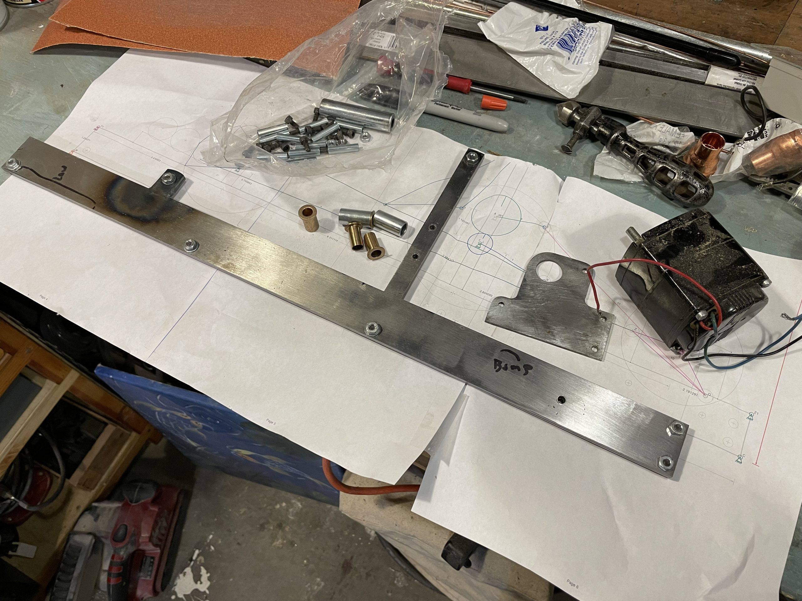
The frame rails are built from 1/8″ mild steel “bars” that I bought at the hardware store. The two vertical pieces are mild steel bits that I had sitting around from other projects that were cut and welded into place. Welding those actually bend the large frame rails in the hard-to-bend direction and I had to do a lot of filing to get them straight. I could have heated them and clamped them to a 3/4″ bar of steel I have sitting around but I didn’t know how well that would work.
The picture of the frame rails includes a printout of the mechanism plans that I created with the Linkage software. The software can print out 1:1 and with care, I was able to get the sheets taped together accurately enough for this project. The only holes in the frame that need to be precise are the three vertical holes on the vertical supports because their distance apart affects the movement of the lifting arm. The motor mounts, etc. are all a bit variable since no movement is changed by those holes being off a little. You can see the bearings that I “trimmed” to size sitting next to the frame with the tubes that they will fit into. Those tubes will be brazed onto the vertical supports. The two rails are screwed together for machining in the first photo.
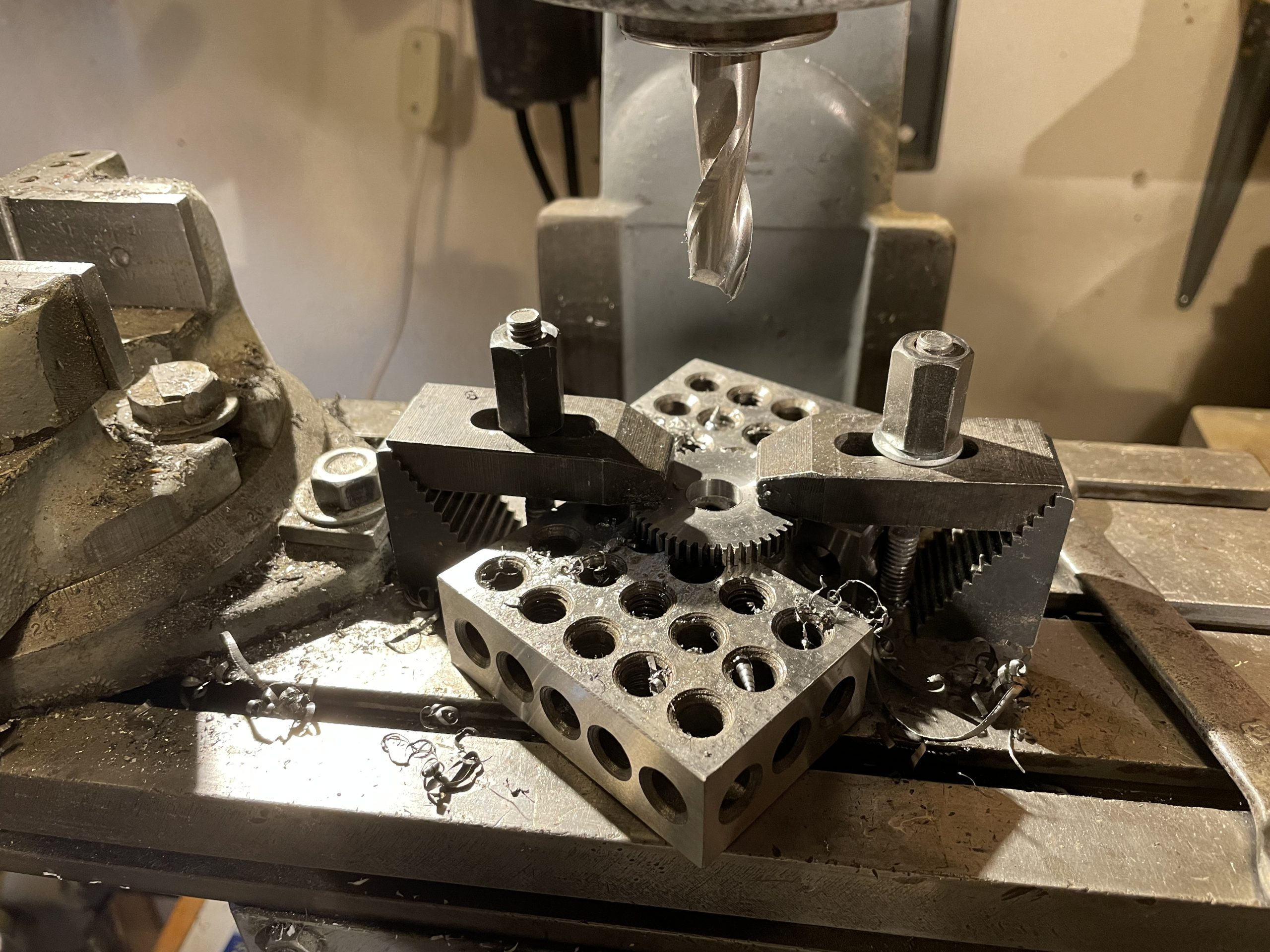
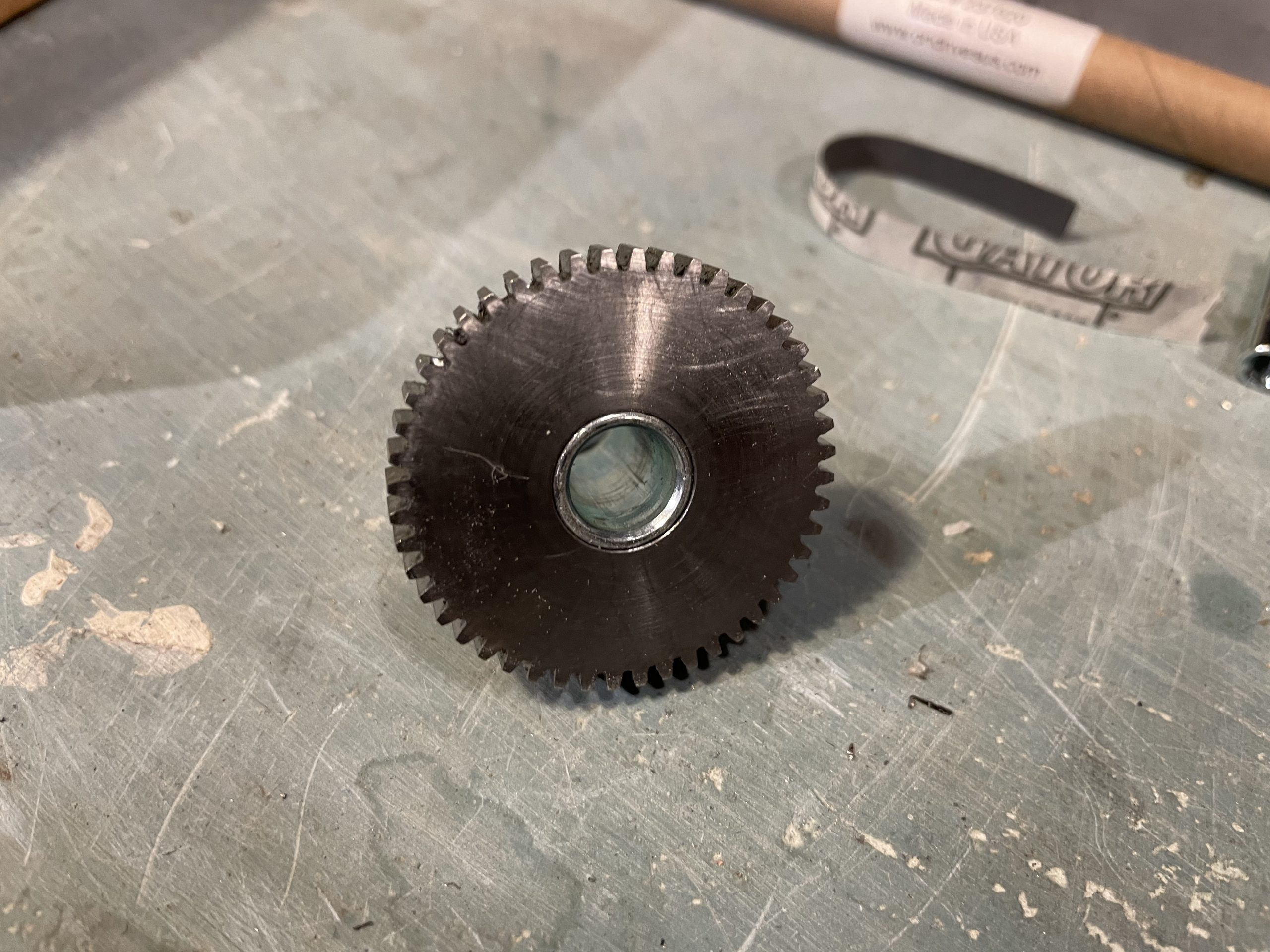
The big gear came with a hole that is the same size as the hole in the small gear. In order to have this large gear have a tube sticking out of it so it can turn on a bearing and so it can have an arm sticking out of it, I needed to drill out the hole. I centered the part on the mill using an edge finding tool then chucked up this giant end mill. It didn’t need to be a center cutting tool because there is already a hole in the gear. I was lucky to just have this tool sitting around in the box of stuff that my dad gave me with the mill. I actually did this twice because the first gear ended up with an off-center hole due to my making mistakes when centering the gear. I’m still learning the best ways to get this stuff done right on the mill (and the lathe too).
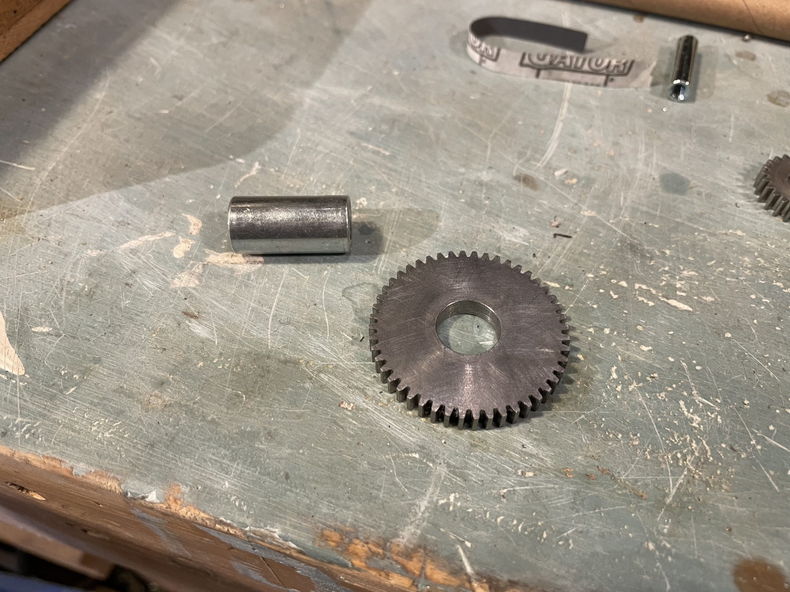
The gears are needed because the arm that drives the lifting arm movement needs to rotate more than 180 degrees before changing direction (it oscillates). A crank can never directly cause oscillation of more than 179.99999 degrees in a drive “wheel” because once 180 degrees is reached, the “wheel” might keep going the same direction or could reverse direction. By having the large gear get driven back and forth through 100 degrees of rotation, the small gear that it drives can then rotate 200 degrees before reversing direction.
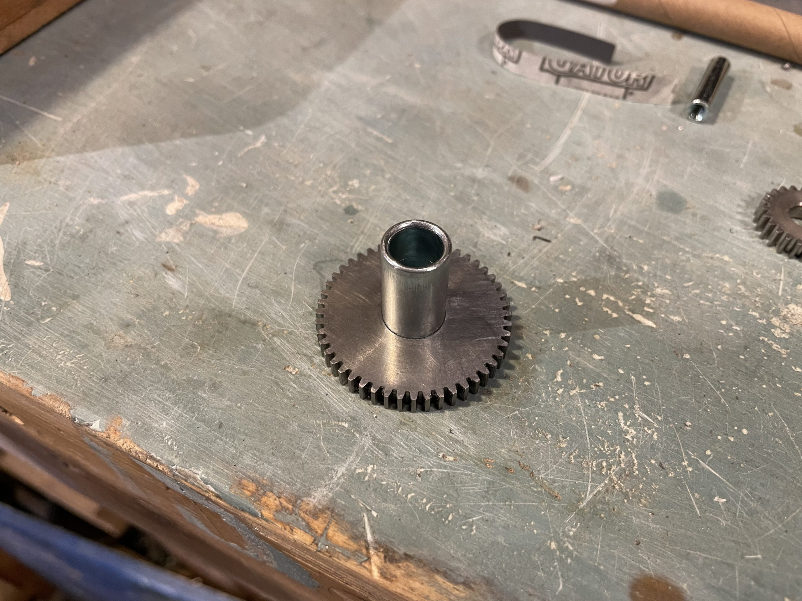
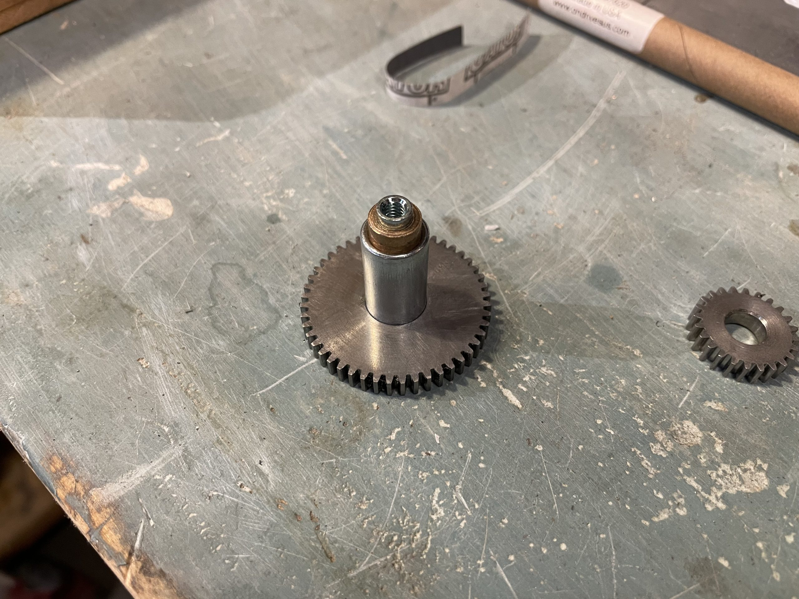
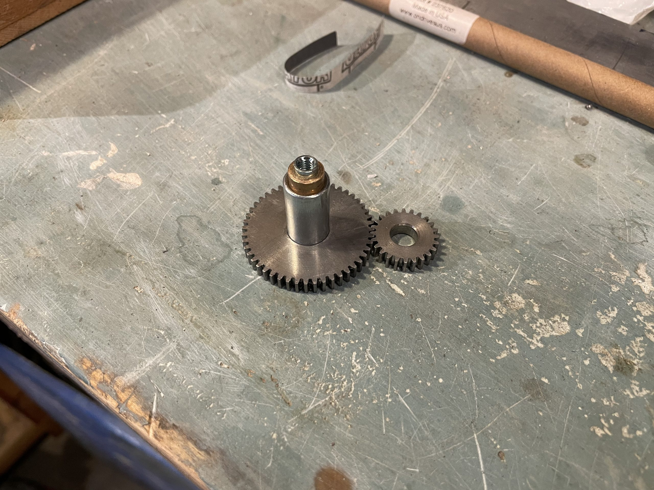
I have a few pictures above the large gear and the tube that goes into it. One of the pictures also shows the bearing which is a solid bronze bearing as well as the shaft that it rides on. The shaft is threaded inside so it can be attached to the outer frame rails with screws. Precision is not important since tolerances are low and since this thing runs at a 2 or 3 RPM.
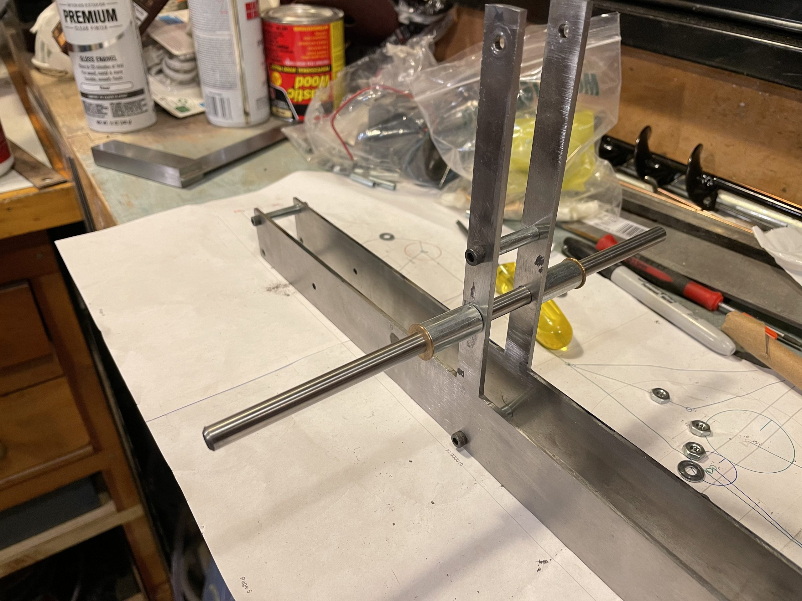
The picture above shows how I was aligning the tubes for the small gear crankshaft. I’m going to skip the part about how I messed this up and bent the supports when I had it clamped unevenly. I eventually got it all straight enough to work fine since, again, this runs at 2 or 3 RPM and has very low tolerances.
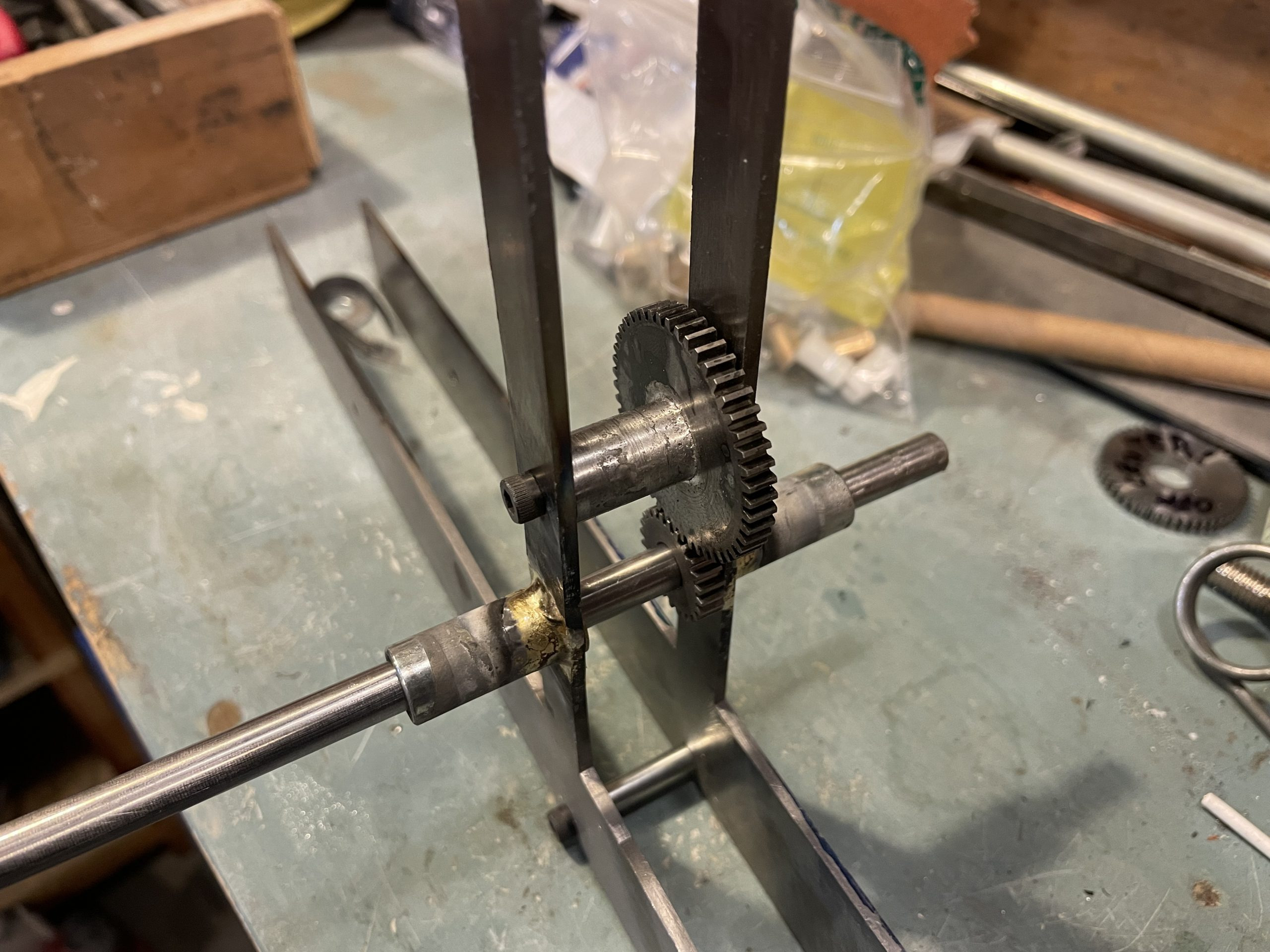
The tubes in place right after brazing look terrible. But the picture above shows everything lined up. Later pictures will show the tubes cut off much shorter and totally cleaned up and shiny.
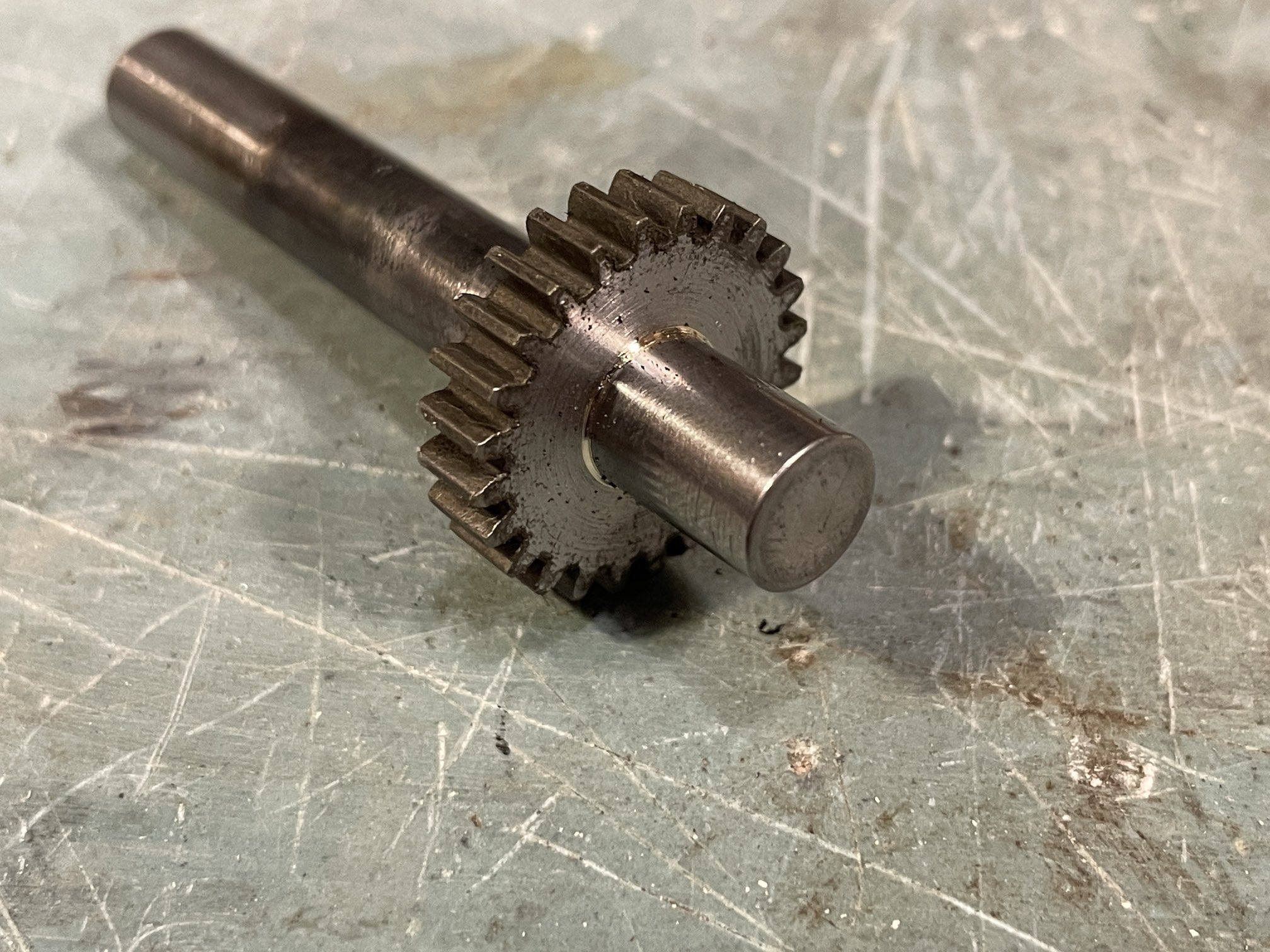
Like the big gear, I ended up using two small gears while trying to get them brazed onto their shafts. The first one was bad because I got bronze brazing material on the teeth. I needed to shave the brazing rod down to a point so I could touch it right into that seam where the gear and the shaft meet without heating up too much of the brazing rod and using too much material. I also rubbed some of the flux coating off the brazing rod onto the shaft before sliding the gear on for the second attempt.