
Mac Version Coming Soon! (in a year or two;)
Now on Facebook
Support the Mac Port on Patreon
Linkage is a free computer-aided design program for Microsoft Windows used for prototyping of mechanical linkages. The mechanism is edited and animated in the same window allowing for quick analysis and modification while working on a design. It is simplistic for a CAD program but that is the intent.
The current version is 3.16.42
Download Linkage files here including documentation and beta software.
Click here for Frequently Asked Questions.
If you have winget installed, you can run “winget install linkage” at a command prompt to install Linkage (and it might work).

Linkage Window and the Theo Jansen Mechanism

Linkage for the Mac (in development)
Mechanisms can be designed with pivot connectors or sliding connectors (that also pivot). Inputs to drive the mechanism can be rotary or linear. The number of connections on a link and the number of links is virtually unlimited.
Before describing the Linkage program any more, here is an example of a real-world mechanism that I designed with it. This is a machine that lifts a 1 inch steel ball so that it can roll back down to the bottom of the machine. This is normally called a rolling ball sculpture (RBS) or a marble run, but there is more lift mechanism here than there is track, so this is more of a kinetic sculpture. First is the Linkage program design being animated, followed by a video of the sculpture running. And finally, a photo of the finished product!
Linkage Software Simulation
Finished Mechanism

The Final Rolling Ball Sculpture
Linkage is a Windows program that has been developed and tested on Windows 7,8, & 10. It has also been run on some Windows XP systems with the most recent service packs installed. There is now a Windows XP specific installer for a version of the Linkage program that doesn’t support the improved screen drawing capability. The XP version of Linkage has also been run in the Wine environment on Linux by at least one user. You can also run on a Mac using Parallels Desktop.
Linkage is a personal development project and its features sometimes change quickly when I have new ideas that seem better than the old ones.
BackhoeMechanism
Blog posts about the development of this program can be found here.
Watch a basic tutorial on how to create a mechanism using the Linkage software.
Some of the Features
- Works like a vector drawing program.
- Has a modeless interface with no mouse tool selection for any operation or action.
- Lets the user create any configuration of links, connections, gears, and chains. There is no limit to using specific types of linkages and mechanisms.
- Gear and chain mechanisms can have gears on moving links.
- Has a visual style that matches mechanisms shown in many books.
- Runs at 30 frames per second when simulating the mechanism.
- Reads and writes .linkage2 files that use the XML format.
- Can move, rotate, scale, stretch, cut, copy, and paste, any set of selected connectors and links.
- Can align selected connectors in many ways including at right angles, any angle, in a parallelogram or rectangle, etc.
- Will optionally snap connectors to a grid and to other objects during editing.
- Has zoom and pan.
- Has unlimited levels of undo of all operations (depending on available memory). Also has a Redo feature.
- Will play, stop, pause, and step the simulation, at any time during editing.
- Uses pivoting connectors as well as less common sliding connectors.
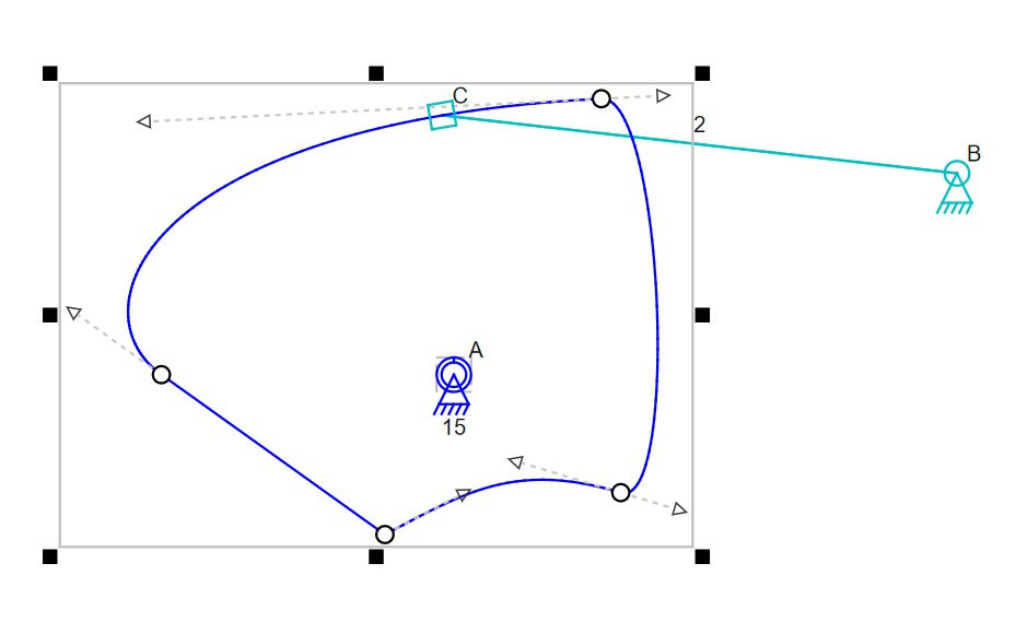
- Supports spline-based cams and spline-based drawing elements.
- Allows for any number of rotating and/or linear (actuator/hydraulic) inputs.
- Allows control of input positions manually during the simulation, if desired.
- Will print hard copies of the mechanism on one page and on multiple pages at 1:1.
- Lets you record the simulation in an HD video file.
- Lets you save a picture of a mechanism in JPEG or PNG format in a variety of sizes. The image can also be copied and pasted into other programs and apps.
- Allows you to assign drawing capability to any connector to visualize its path during simulation.
- Will open and simulate a wide variety of included sample mechanisms.
- Automatically displays dimensions of parts in mm or inches in a way that is suited to manufacturing individual parts.
- Will draw dimension/measurement lines manually.
- Will draw points and lines separate from the simulated mechanism.
Splines and cams are now in the app! Cams are essentially just closed splines that have a sliding connector sliding on the spline.
Cam Editor
Images of Various Mechanisms and User Interface Elements

Backhoe Sample

Movement Amplifying Geared Mechanisms

Watt Linkage with Measurements, Points, and Lines.

Various Types of Alignment Tools

Hint Lines Show How Alignment Operations Will Behave

Automatic Dimensioning on Klann Linkage

Image-Based Menu for Dropping Elements Into a Mechanism

Multiple Gears and Ratios

Parts List Display
If you got this far and the Linkage program looks interesting, feel free to let me know what you are looking for, and what type of project you are working on. I pick new features for the Linkage program from user suggestions, and I would love to hear about features that I didn’t consider, or have never imagined.