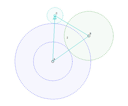
I have a little bit of the user interface working.
I took out an optimization feature where joining a lone connector to another connector would just discard the link that was part of the lone connector. Now, a lone connector might have a link that is a gear, so I can’t just discard them. If that’s not clear, look at it this way; a lone connector has a link, but the link has only that one connector is is therefore invisible. Before now, if that lone connector was joined with some other connector, the underlying link for that lone connector was meaningless and would just be deleted internally by the software.
In the image up above, I added an anchor with a link, and then made the link a gear. That’s connector C and the link went to connector A. Then I added a lone connector and made it a gear that I then dragged on top of A, automatically joining them. That gear link at A that is blue is it’s own link, but the number isn’t shown yet because that link has only the one connector. Anyhow, I set a ration between C and A and that’s why there is a small green dotted line circle at C and a larger blue dotted line circle at A. Then I added another connector and combined it with link 2, which was between C and A. Tat gave me the connector B. Finally, I added alone connector and made it a gear, and joined it to link 2 at connector B. That’s why there is the off-green circle at B. Sine I gave a ratio for the A to B gear connection, I get two blue circles, one for meshing with C and one for meshing with B.
I’ll post more later when I have these things working better.
So far, only the user interface is working a little bit. I have not tried to simulation any of this. That should be very easy, since it involved a simple link rotation for any one gear. Of course, I’ll have to detect when gears conflict with each other, but that too should be easy. It’s really just a lot of typing and testing to make sure that I didn’t miss anything.

