I was just having a discussion with my dad about gears. Every now and then, I think about how to add gearing to the Linkage program and I think that I now have a way to do it. I’m writing down the ideas for future reference, and because writing down this sort of thing helps me find the flaws in the design.
Gears would be a link, just like any other. The circle, or other representation of a lone gear would be of some fixed size. There would be no point in sizing the gear if it’s not meshing with another gear. The user could then click on the circle to select the gear. Okay, so maybe it needs to be some special sort of circle. I’m not sure yet. It at least need a mark on it so that the rotation can be visualized. The center of the gear is the one and only connector allowed, Or maybe there can be multiple connectors and all but one are draw as spokes out from the center. That’s an interesting idea.
A gear, since it has connectors, could be connected to other links. If I chose a “fixed to…” sort of mechanism, then the gear could be fixed to other links and would move them, or move with them. Otherwise, it would just freely rotate on it’s connector.
Now the trickier part; two gears need to mesh. I think that the user would need to select the two gears and then type in a ratio. Doing this sort of thing by dragging is not how someone would design a geared system. Once two gears have a ratio, they would get circles draw appropriate to that ratio. if there are three gears with one meshing with both of the others, it would be drawn with as two circles if needed, to properly show the two different gear ratios.
And finally, like any other link, one that has a rotating connector would get rotated like any other link on that connector.
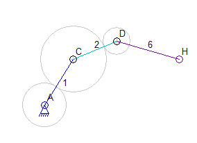
In the picture above, I added some circles to a mechanism to show how the gears might look. Connector A is an anchor and has a gear connected. Connector C also has a gear, and since a ratio was set (in theory) the A and C circles are drawn at the correct ratio. Link 2 is somehow connected to the gear at C so that it rotates with that gear. I’m not sure how this will be done, but it will work somehow. Anyhow, these are all connected in some way that would move links 1, 2, and 6.
One additional idea I had was to let a gear have more than one connector. Then another link would not need to be attached to the gear to have other parts. If gears just have more connectors, the gear C above would actually be link 2, not just attached to it somehow. Also, that mechanism above is not too realistic, since it shows how gears might rotate links but doesn’t have one gear just rotating without some link sticking out from it.
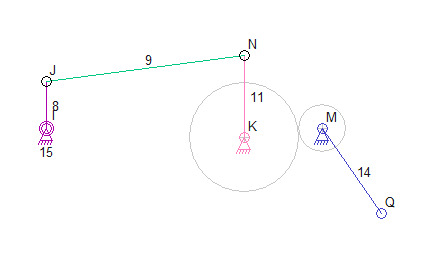
Here’s a more interesting mechanism:
In the picture above, rotating link 8 moved 9 that then moved 11 back and forth. Since K is connected to M with a gear,and because M has a much smaller gear, connector Q on link 14 moves a long distance. In fact, it could move back and forth by more than 360 degrees (if I draw things to the proper scale.
The next step is to write come code to handle the user interface. But I really need to decide if the existing “fasten” feature will be used to attach a link to a gear, or if gears can just have multiple connectors. I think that the “fasten” mechanism makes more sense because a link could have any number of gears on it. Ah, but then again, only the connectors that move with the gear need to be part of the gear. Oh well, I’ll mull it over for a while.


