I have the user interface in the Linkage program working somewhat. I have a serious dilemma with the simplicity of it. The concepts are good, but the details are troublesome. I’ll explain.
Various gear Configurations
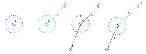
In the image above, there are four gear interface situations shown.
- The user can always add/insert a gear into the mechanism all by itself, as seen with the gear at connector A. This won’t change.
- A gear is a link, not a connector, so it can be a link with other connectors besides the one at the center of the gear. Link 2 has a gear at connector B. If the gear is rotated, the entire link is rotated because a gear is a link. The user created this situation by adding link 2 with no gear and then changing the properties of connector B to be a gear. That property change really changed the properties of link 2 to have a gear around connector B.
- If two links are connected to another link at a gear connector, the third gear in the image is what shows up. Link 3 has a gear at connector G and link 4 was then joined at connector G. The color of the gear and link 3 are the same because they are the same link. Remember, a gear is a link.
- The user can finally connect two links, like 5 and 6 in the picture, and then connect a gear too. The user created links 5 and 6 and joined them at connector D. A gear was added to the mechanism separately and then also joined at connector D. There are three links, 5, 6, and the gear at connector D. If the gear rotates, the other links do not rotate with it because they are not the same link as the gear.
The concept that will be hard to teach is the one where a gear is a link and can have other connectors, not just the one at the center of the gear. Even in the case of connector A in the image, there is a link with a single connector A. The link number is not displayed in tis case, although I might change that in the future for gear links.
So Far
Now, the user interface works pretty well so far. I followed the steps I mentioned in the numbered list to get those various parts of the mechanism. But I could simplify the steps in some cases. For instance, the user interface will not allow the gear property to change for connector D because the program doesn’t know which of links 5 or 6 to change to be the gear link. I had to add the gear separately and then join it at connector D. I could change the interface to let me set the gear property for connector D, thus adding a new link that is the gear. Would that be confusing? I think so, because doing that identical property change to a connector that is not connecting links would result in the link becoming a gear link, like when connector B was changed.
But maybe the concept of the gear being a link is too much information for a user. Maybe I just describe the effects of adding a gear in these various situations and not mention that a gear is a link. The only time that I would describe it like that is when I add a link number to gears that have only a single connector, like at connectors A and D.
Link Numbers on “Lone” Gears
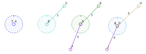
The slightly different image above shows link numbers on the two gears that are not part of any of the obvious links. I just threw in the numbers 7 and 8 for the gears at connectors A and D respectively.
Link Numbers on All Gears
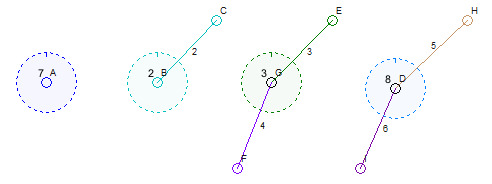
Another idea is to always show the link number with the gear. Then the user can plainly see what link will move with the gear. This is becoming a better idea the more I think about it.
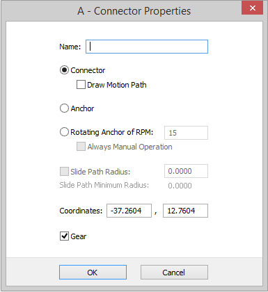
For reference, this is what the connector properties looks like right now:
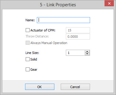
I think that I should show the link number or name next to the gear checkbox, and show the word “(New)” if a new gear will be added at the connector. That might be sufficient. Right now, a link can also be changed t be/have a gear using the link properties dialog box:
Checking the Gear checkbox will then add/create a gear at any of the connectors of the link.
Another Idea
What if the user selects a connector and a link at the same time. Although I won’t let them see a properties dialog box in that situation, I could allow that and show properties for making a gear, with no other actions available.
No matter what else I do, I am going to remove the gear option from the link properties and not document the fact that a gear is a link with one or more connectors, one of which is the center of the gear. The action taken by the user will determine how a gear appears in a mechanism.
Finally
Finally, I will probably change gears to use solid lines. No one draws dotted lines by hand, so gears appear as solid lines in all of the online images I’ve found of mechanisms with gears. I think that dotted lines might have some other meaning, or just be too unfamiliar to users. But as usual, I’m not sure yet.
If any users read this and understand it, let me know what makes sense to you! Send me an email or contact me using the contact form over in the right column (you must be registered to send a contact form to me).

