
I’ve been posting videos on YouTube () showing some working features and some failing features of the Linkage app for the Mac. Here is one of the latest:
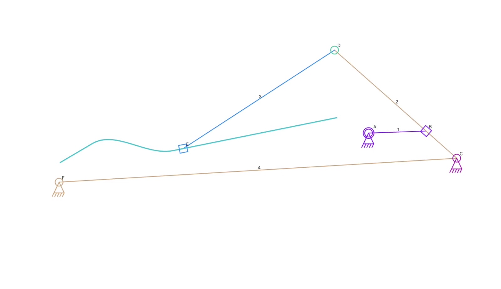
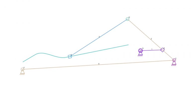
Even though this looks like a simple mechanism with a sliding quick-return that makes a link oscillate, thus moving a sliding connector along a spline, it’s actually rather complicated. I’ll quickly describe how the simulator works in the next paragraph, then discuss why this mechanism is interesting.
The simulator maintains a list of all links and iterates over it to find pairs or triples that can be combined into a composite link. If you imagine three links in the shape of a triangle, these can be easily combined into a composite since the three links will act as a solid unit during simulation. This three-link triangle even works for three actuators in a triangle since a composite link is simulated to get its shape before it is used as a solid unit in the rest of the simulation. Various types of composite links get created this way. Since a composite link could be part of a larger composite link, the simulation data ends up in a tree structure with a single link at the root that represents two or three components. Then, for every step of the simulation, the bottom-most pieces get resolved before their parent composite links get resolved. The processing trickles up from the leaves to the root. The simulation code never tries to resolve a composite link in a way that keeps the anchors in place, so one final step in the simulation is to move the entire mechanism back to where the anchors require it to be.
This mechanism in the video is interesting because it resolves the quick-return sliding connection near the input (motor anchor) by doing a calculation that moves the sliding connector, the anchor, and the link between them to a position where the sliding connector is on the path. It would be extra math to do that, then immediately rotate it back. And it would also require additional code to calculate the rotation angle, then rotate the path link the opposite way to end up at the sliding connector. That extra code would need to figure out which composite link has anchors, and it would need to run repeatedly for multiple composite links. It’s less processing work to rotate the composite link that contains the sliding connector and let it all get moved back later.
Okay, so I just wrote about how I want to avoid extra processing work. But since the spline is not in the list of links, it isn’t altered at the same time as the composite links. In fact, the spline is a part of the original mechanism data and is not part of the simulation data. I opted to make a copy of the spline at the moment it is needed and to move that into the correct position at that time. I didn’t make the clone spline part of the link it is fastened to, in this case the ground, because if it were fastened to just a connector, it would be lost. I may rethings that, but for now, the clone spline is moved into position, the sliding connector calculations are done, and the composite link is repositioned based on the result.
It was all a bit complicated to work on because a spline can be fastened to a connector and if it’s an input, the spline needs to rotate to match that input rotation. If it’s fastened to a link, inclluding the ground, the spline needs to rotate to match any rotation of that link, and it needs to be moved to match any change in position of that link. for a standard connector, the spline will move but never rotate. Yeah, that’s weird, but I do allow elememts in the mechanism to be fastened to a standard non-input connector so they move but do rotate at all.
The next step in development of sliding connections is to handle a link that has three sliding connectors determining it’s position. That’s not as complicated as it seems if two of the slidig connectors use the same path. That same set of calculations can also work for a link that has two sliding connectors and another link connecting it to determine it’s path – in either case, the link will apear move move along the slide path as the mechanism runs through the simulation. But for the simulator, there needs to be test to “see” that set of conections in order to build tghe composite link from the individual elements.