I was working the last few nights on an update to the linkage design and simulation program. I have started the process of adding linear actuator support. Until now, rotating inputs were the only type of input available.
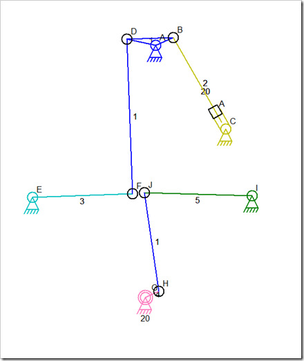
I have a working mechanism although I have no way to change the distance of the actuator movement. It is stuck a small distance from one end of the link as you can see in this picture:
The linear actuator is the yellow link numbered 2. It has two lines near one end that indicate that it is an actuator and to show the throw distance. Throw distance is the distance that the actuator will move. There is also a connector being drawn in this version over the end of the throw lines that will be draggable a few nights from now. I’m having trouble managing that connector because it is not a real connector and should not act like other connectors in most situations. I am only using a connector because of all the code that keeps track of selected connectors for dragging purposes.
The mechanism in the picture works and is part way into the simulation. The line from B to C doesn’t reach C because the actuator is extended a little.
The linear actuators only work in the configuration shown. There is other simulation code for handling the sliding connectors that will need special handling of the actuators.
Once the linear actuator code is working and the throw distance is adjustable using the faux sliding connector, I will attempt to add some special sliding controls to the user interface so that a mechanism can be manually controlled. This will make the simulation of a tractor bucket or other user controlled mechanism more realistic and =certainly more interesting.


hi Dave,
I try to install your program, but its say that cannot install on XP
Why
Abraham