I’m working on simulating the Assur Triad using an iterative algorithm. Click here for an older post about the problem I’m trying to solve. The algorithm essentially treats two of the three “legs” of the triad as a 4-bar mechanism and simulates it as one of the legs is rotated through all possible positions. Well, not ALL possible positions because that would take an infinite amount of time for an infinite number of points. What I’m doing is calculating 360 steps for 360 degrees of rotation.
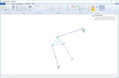
Above is the linkage mechanism. Connector C5 is rotating around C4 so it’s location is known for any step of the simulation. That gives us a triad, a link with three links connecting it to three known locations.
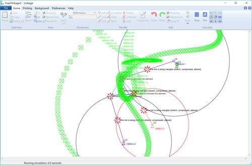
The two larger dark blue circles in the picture above around the two connectors used to form a 4-bar linkage. One of those connectors is used as the rotation input of the algorithm. The connector on the triangle link is rotated, mathematically, through 360 degrees in 1 degree steps. The 4-bar simulation results in a set of 360 points that represent the curve path of connector C3. Of course, C3 cannot be in all of these locations and is also restricted by the red circle. The algorithm will eventually find where the curved path of C3 intersects that red circle. That is the only actual valid location of C3.
It seems senseless to calculate all of those green debug markings. So the first thing I’m doing is only testing a set of points for an input rotation 10 degrees to either side of the starting point. Note that all of the starting points for the mini-simulation of the 4-bar mechanism are based on the previous known locations of all of the points, either from a previous step of the simulation or from the original locations if on the first step of the overall sim. it’s a very good bet that the new location of the points will be very close to the previous locations and not jump large distances.
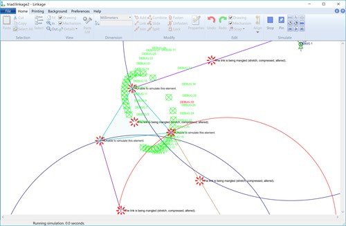
The result of the small optimization of using only 20 degrees of rotation is shown above. I have no idea if this is too many steps or too few. Experimentation will tell.
The next step is to find the closest point, which is getting saved right now and is represented by the red debug marking, and then do the same process again but only between the point before and the point after it. That will give a more accurate potential location for that connector. This will get done multiple times to find a point that is close enough to be within the overall “stretching” tolerance of the simulation. Links are allowed to stretch and compress by a ten-thousandths of an inch just to allow for rounding errors in the various equations.
So it’s almost working. I narrow down the possible locations for the point but it’s off by too much after a small amount of movement. It might be just that I’m making a mistake somewhere in handling how I move the parts of the mechanism. I’ll have to track it down since this looks promising and seems close to working.


