
![]()
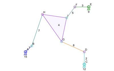
Someone told me that what I’m having trouble with is called an “Assur Group” and some research led to me think that its more specifically called an “Assur triad”.
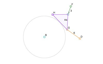
The mechanism above is what gives me trouble. Each of the connectors B, D, F, can be simulated and their locations are known for any step of the simulation. But to calculation the location of G, H, or I, the simulator needs to know the location of one of the other two connectors (G, H, I). Since one needs to be known before the others can be calculated, and because that applies to all of them, none can be calculated. Well, at least not using the simulation math that is in the Linkage program.
The solution is to find someone who can write the 9 simultaneous equations for me, or whatever math is needed, to just give me the answer to the location of at least one of those connectors G, H, or I. The alternate solution, which is the one I am investigating, is to take the four links 5, 6, and 7, and run an iterative sub-simulation on it to figure out its configuration.
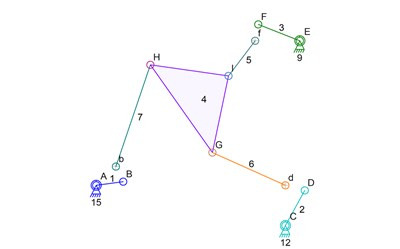
The next step in this analysis is to examine the regular simulation step and how it affects the mechanism. Here’s what happens when the simulation step is taken for then entire simulation:
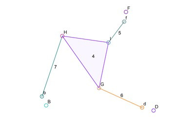
Only the new locations of D, D, F, are known. I show the original locations of those connectors with lower case b, d, and f. The triangle link 4 is also just sitting at its original position. Now for the sub-simulation of the triangle link 4 and its connecting links, the rotating inputs can be removed. They are already at known locations and the new locations of B, D, F, are also now know. Here’s a simplified drawing with extraneous parts removed:
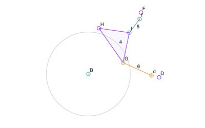
Now to get to the important parts of the sub-simulation algorithm. The sub-simulation is going to pick a 4-bar mechanism out of this Assur triad and then rotate one of the links to find all of the possible positions of one of the connectors on the triangle link 4. Picking is easy since there is no specific need to pick certain links. I use the first connectors or links that are in computer memory. Of course, link 4 must absolutely be picked for this since it forms the important connection in the 4 bar sub-simulation mechanism. Links 4, 5, and 6, are going to be the 4-bar mechanism (with the ground being the invisible fourth bar, as is typical of these things). The previous locations of connectors D and F are very important for helping optimize the algorithm so those will be shown in the drawings. Interestingly, the previous location of B and the previous configuration link 7 is not needed at all. Only the length pf link 7 is used and is represented by a circle around the new location of B. Here’s a drawing of what we know so far:
The links 4, 5, and 6, are still shown in their previous locations because their new locations are not known. The sub-simulation algorithm is now going to use the visible 4-bar mechanism to determine all possible locations of H. The sub-simulation will use the lowest labeled connector of D or F to be the rotating input to this sub-simulation. To be efficient, it will use the previous angle of link 6 as the starting angle of this sub-simulation. Unfortunately, if link 6 is kept at its starting angle, the parts won’t fit together. That’s fine and the algorithm can handle it just fine. For this explanation, I will change the angle to get to a good looking starting point:
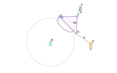
Now it gets interesting because the drawings are not showing a ready-made solution. Clearly, H is in the wrong location for all three of the triad legs to fit. The sub-simulation will now rotate link 6 around connector D to figure out all possible location of I and therefore H. I’m going to turn D into a rotating input anchor in the Linkage software and also make B and F into anchors, so the regular simulator can do the work for me. remember that link 6 did not work as-is in its staring position because link 4 then didn’t reach link 3? That means there will be a gap in the simulation. the curve drawn by H therefore has a gap in it:
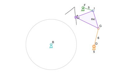
The curve is show above in black. Now there are a few problems to handle at this point. the obvious one is that the curve crosses the circle around B in two places. That will be easy to deal with because the previous location of H is still known, and the algorithm can pick whichever is closest. The problem that is not obvious in this picture is that the configuration of 4, 5, and 6, can be different from what we see here. Using the starting angle of 6 and then 4 as a basis for the initial locations of the links in the sub-simulation should work. But I will need to be careful to ensure this is true. Here’s a picture of a perfectly valid sub-simulation where the links are still all connected in a valid configuration, but the results are not what I want:
I will need to iron out the algorithm and deal with this if it somehow becomes a problem. But for now, using the previous angles of the parts as starting angles should work.
The algorithm is not done if we are examining the details. But superficially, the point where the curve crosses the circle around B, and it being the closest point of the two to the old location of H, is the point where H should be. The links can then be rotated and moved into their new locations are finalized.
If we examine the details, the algorithm still has a tony bit more work to do. The point where the curve crosses the circle is not always a point where H was computed! H moves in steps and one step might be outside the circle and the next step might be inside the circle. if the steps are too far apart then the line between these steps might be cutting corners. the algorithm really needs to find the two points and then rerun the sub-simulation in those areas using finer movement. The way I may do it is with an adjustable rotation “speed” of D during the sub-simulation. Once H crosses the circle, the algorithm will look at the distance of the jump and will undo the step it just did. Then it will step again using smaller changes in the angles until it crosses the circle again. If the jump is not too big, it will go back to the original step size and continue from where it is.
That’s it. That’s the sub-simulation algorithm. If it works, I will have the only software around that is free and simulates Assur triads and therefore Stephenson valve gear for steam locomotives. Now I need to find time to write it!
And yes, you did see a picture in there where the connectors change their labels. I’m using the Linkage program to create the images and when I change things in th4 mechanism, like copying links and then use those copies to replace the originals, the labels and colors get changed. Then again, if I actually type a label, then it would never change. And if I pick a color, it won’t change either.

Hey, Dave! I’ve been struggling to simulate some linkages that doesn’t include a four-bar circuit. Any thoughts on how to solve the Double-Butterfly linkage, for example? (shown here https://www.youtube.com/watch?v=adoHtKAndnY). I’ve just started reading about these special cases and this article is my reference for now http://sci-hub.tw/http://mechanicaldesign.asmedigitalcollection.asme.org/article.aspx?articleid=1444888
Unfortunately, the triangle links with three links to them, are impossible for this software to simulate. This is a case where the simple algorithm I use to predict the position of a link fails if there are more than two outside links determining the position of a third. As soon as there are three, simple algorithms like circle-circle intersection test, will fail to give a solution. If you want more info, feel free to email me. I have also described the problem in some older blog posts.
I’m reading the paper. Maybe it will give me some insight into how to handle these types of mechanisms. Even then, the mechanism in the video is more complex than a simple triangle link problem. It has multiple elements that team up to make the whole simulation much more complicated. I’ll post something if I find a solution for this. Until then, the Linkage program can’t simulate this sort of mechanism.
I looked at the paper. It definitely describes the complexity in simulating this type of mechanism. My math skills are lacking and I don’t know how to go about using any of their equations to make the Linkage program handle these complex cases.