

See log entry #1 here.
I have made a bit more progress. I added cranks to the gear shafts so that when the gears turn, the cranks turn. The large squarish arms on the big gear were made oversize so I could get the hole in the right spot based on the angle of the arms. Since the gear teeth are large and since the angle between the small gear arms and big gear arms is critical, I had to get all of the parts finished except for the final hole in the big gear arms.
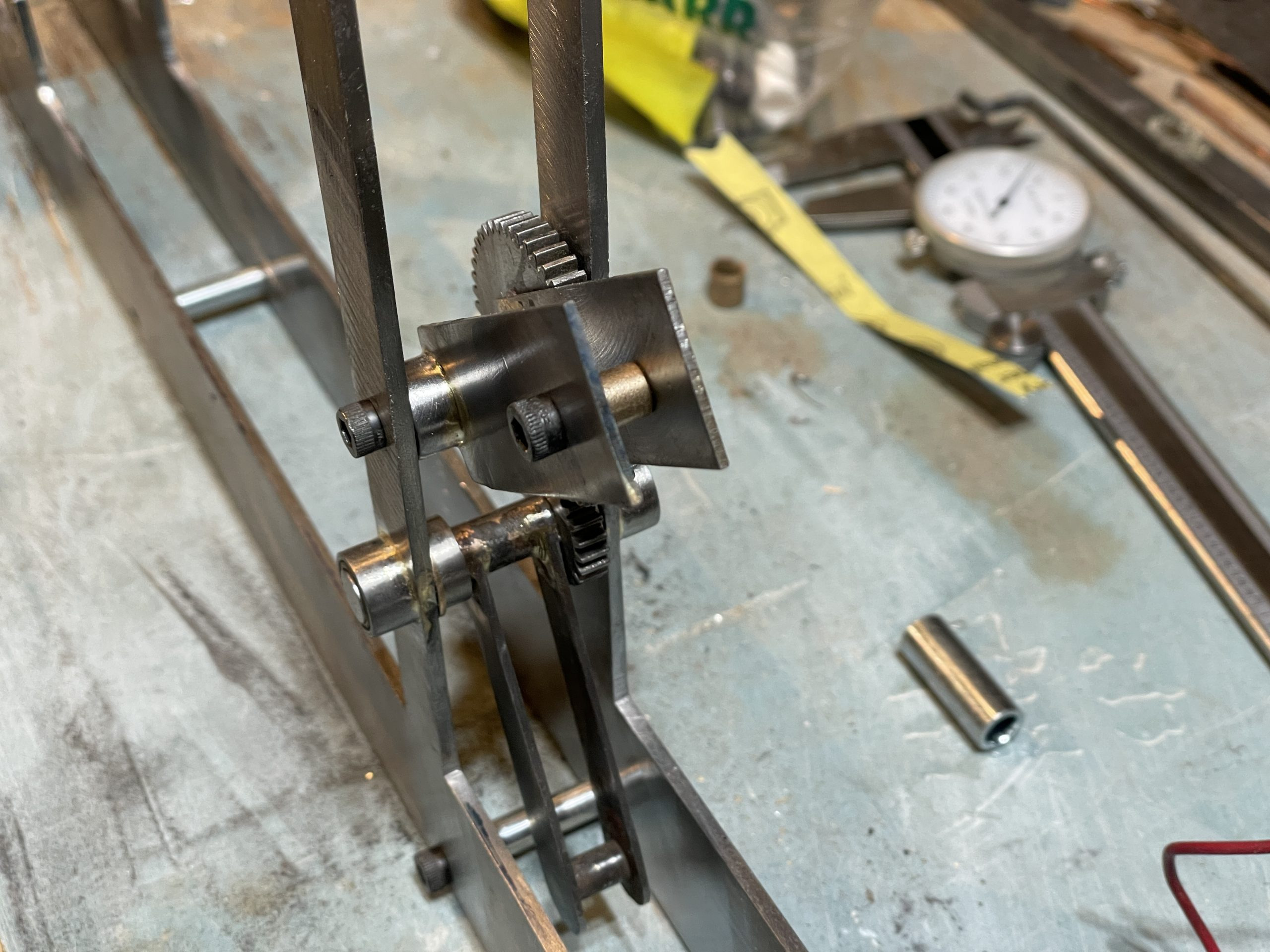
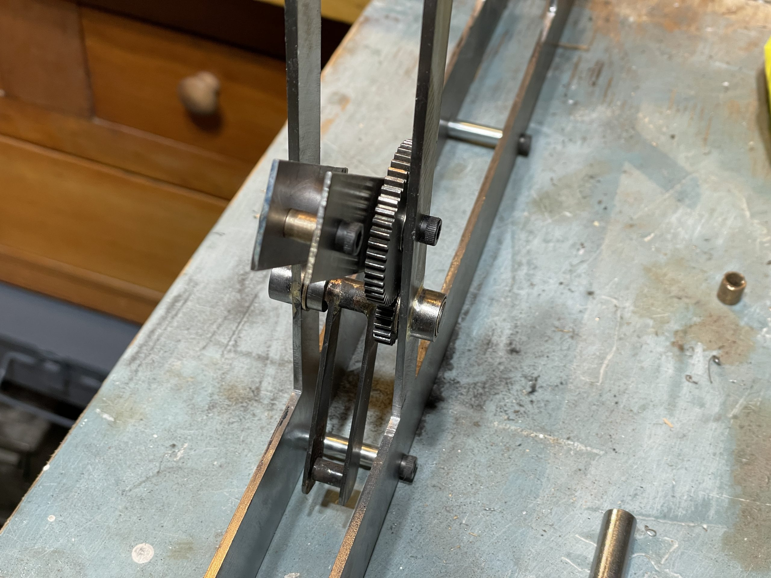
The motor crank is made with a tube that slides over the motor shalf, an arm, a crank journal, another arm, and a journal that drives the small lift at the end of the entire machine. The picture below shows the first parts fo the motor crank in close to their final form.
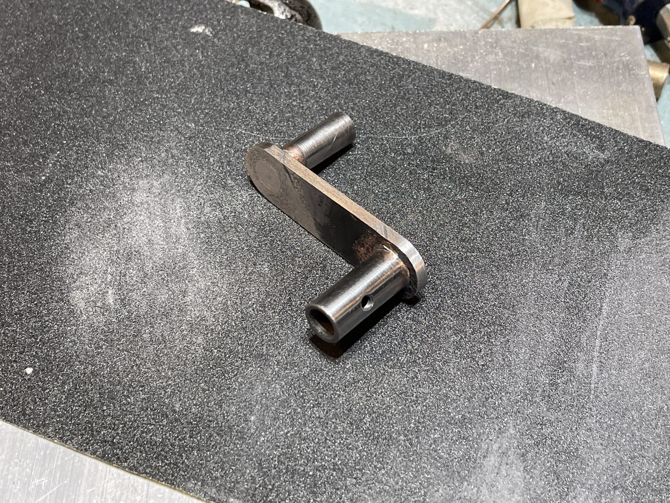
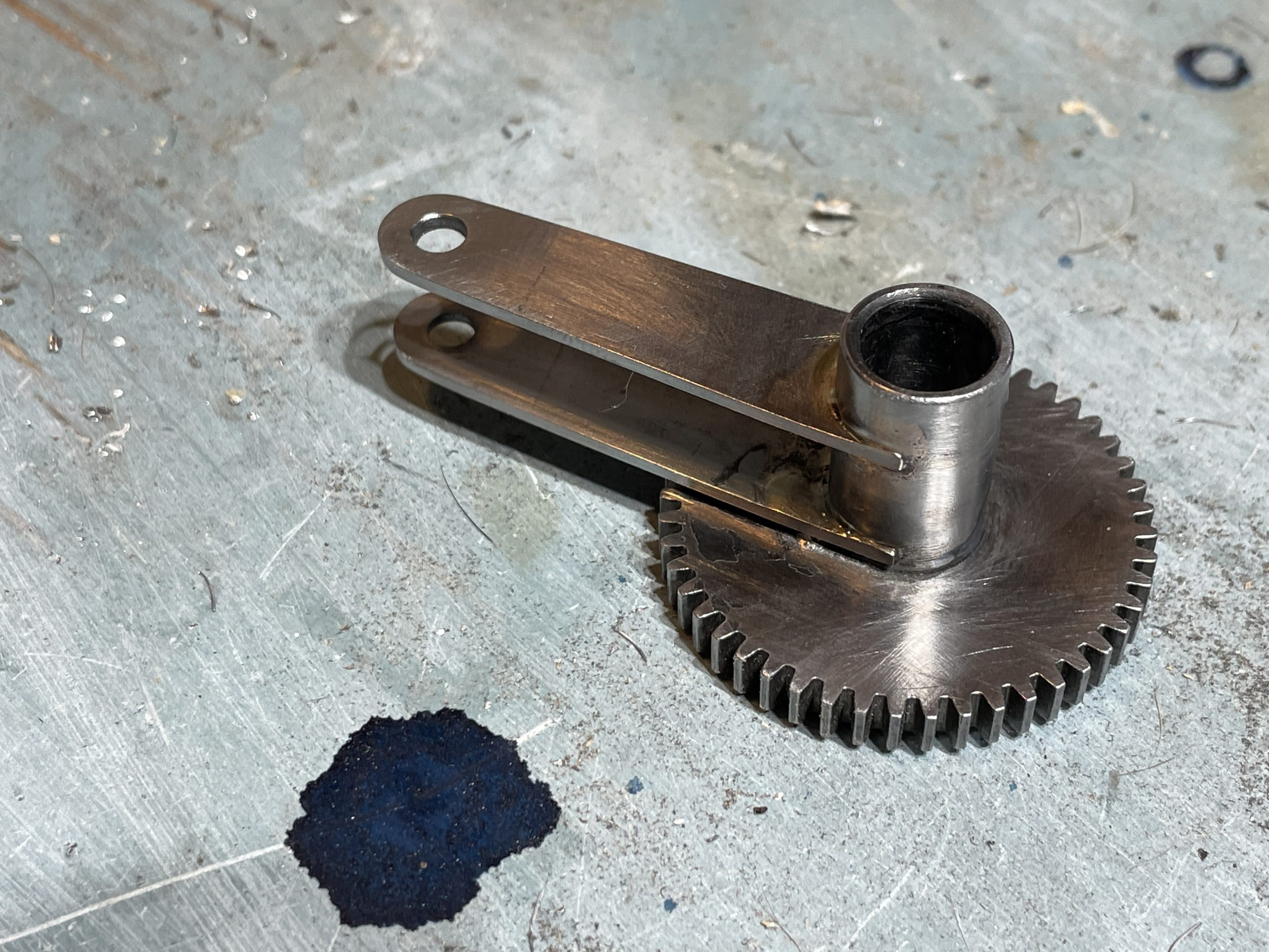
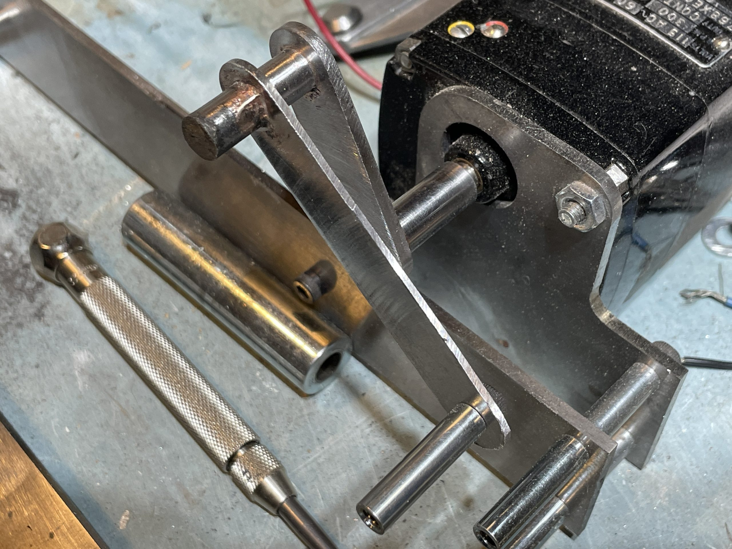
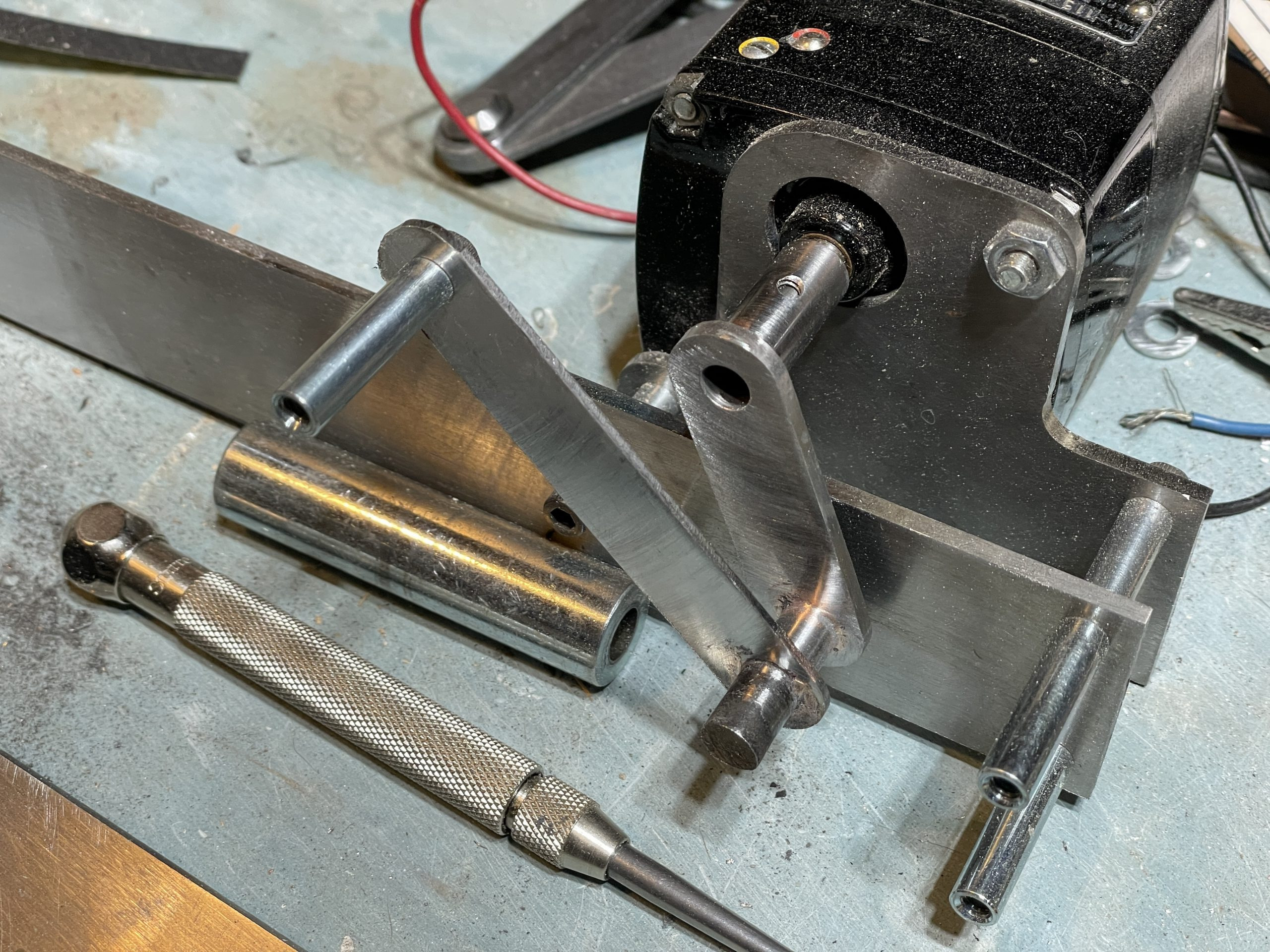
Since the motor drives a crank with two journals and the crank is not supported on both ends, I made the arm for the second outer journal go straight to that journal and not go through a point that is centered on the motor shalf. Automobile cranks have support bearings between each journal but I dont have the room to do that in this machine. Below is the partially finished and then finished motor crank (except for a little needed polishing and maybe some filing where brazing meterial is still on the parts and in the way of proper operation). The outer journal is very thin with a thick washer. The thick washer let’s me use a flat head (countersunk) screw. This outer journal barely fits next to the frame of the machine.
The conecting rod that connects the motor crank to the big gear arms will be made of separate parts brazed together. The first part is the motor crank end. The end of the connecting rod is made from multiple parts, one of which will be screwed onto the end of the rod around the bearing. The bearing is a tube of bronze bearing material that is split in two for installing around the journal on the crank. The end of the conecting rod is made by taking two rectangualr pieces of steel and then drilling, counterboring, and threading of the various holes so they can be screwed together. Drilling and tapping came fist and there are somer pictures of the parts as they are being made and test fitted together.
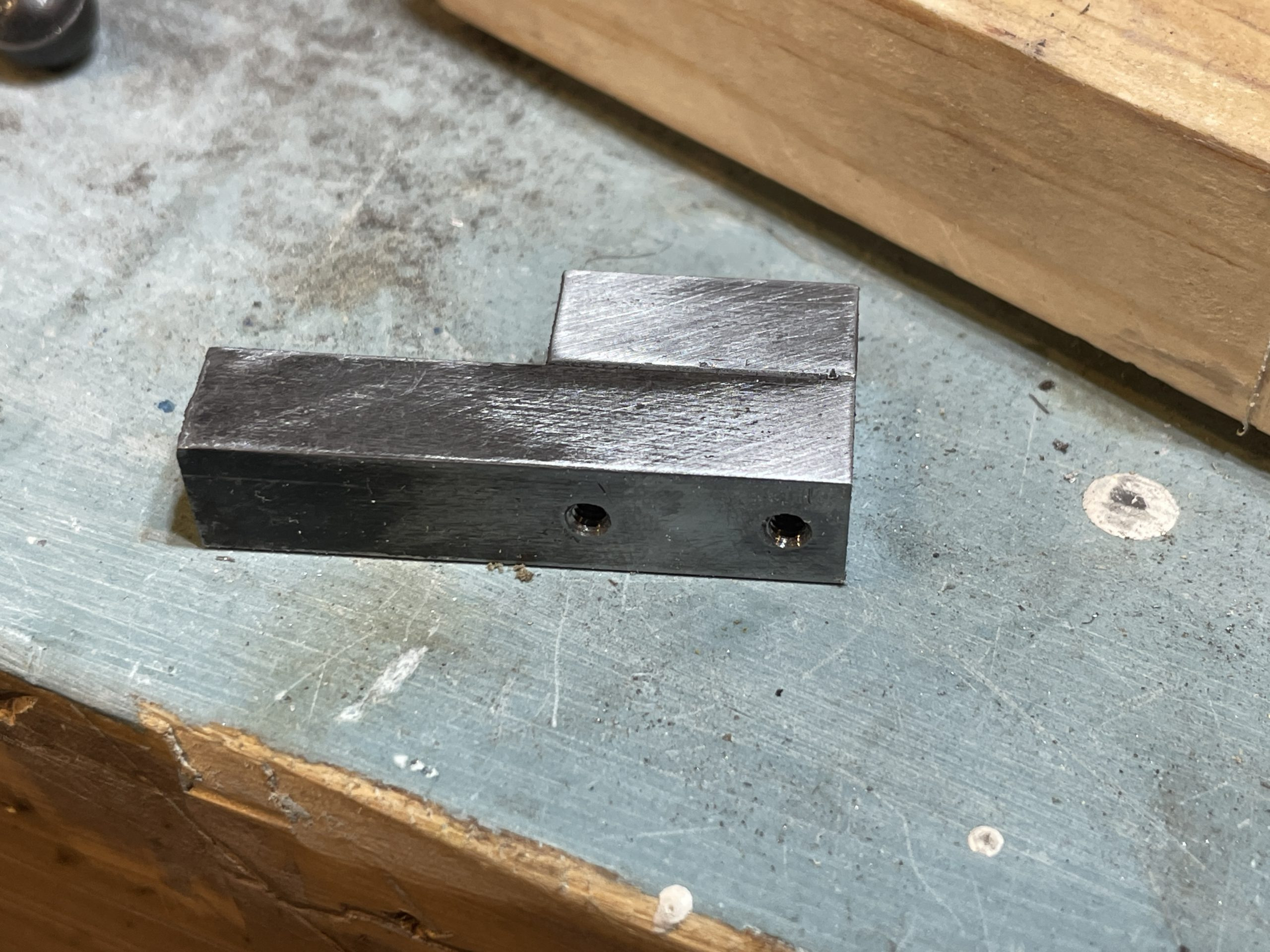
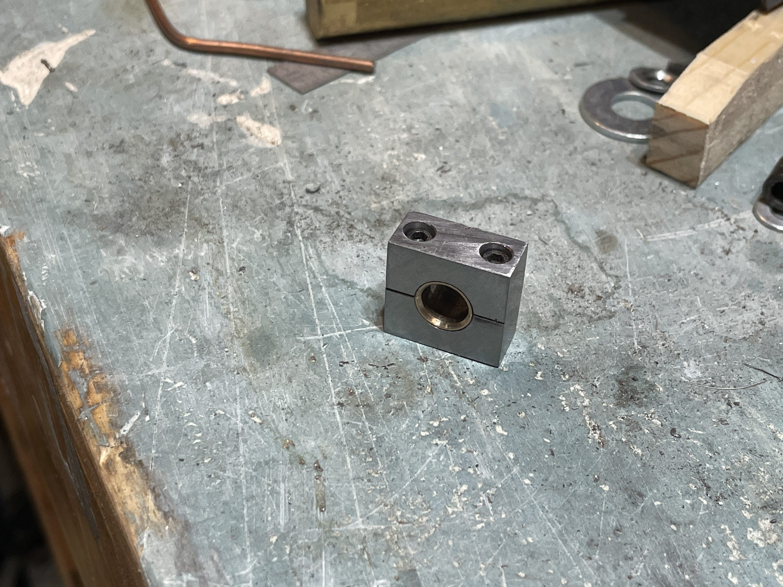
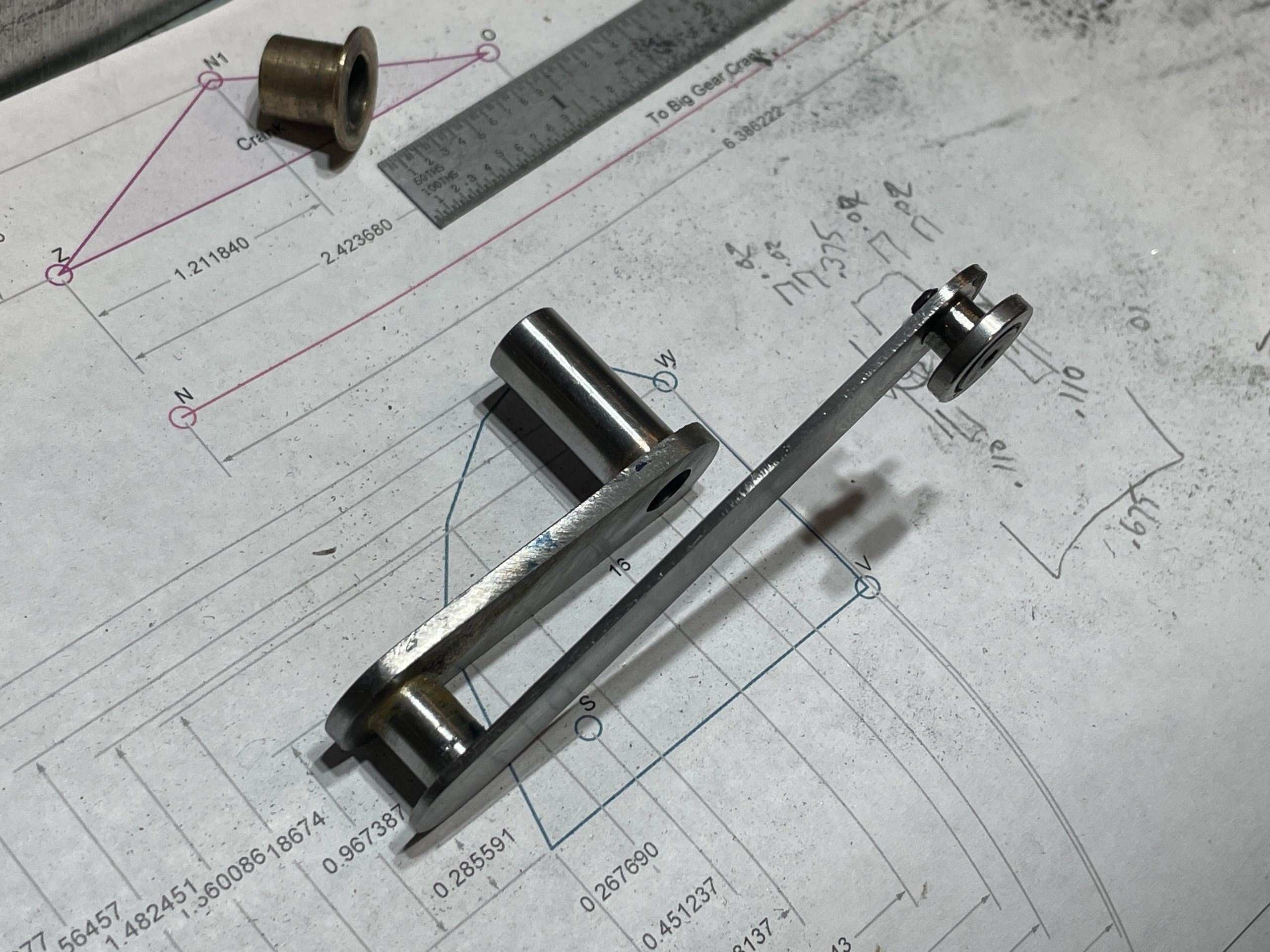
The end of the connecting rod also has a large hole perpendicular to the screw holes that holds the bearings. This will clamp arond the crank journal. The picture below shows these parts including the #4 screws and the bearings. The bearings are beveled or recessed on the ends to allow for the small amount of brazing material that still might be on the crank journal – sometimes it’s easier to account for a little crud on the parts than to make those parts perfect. The bearings were made by making a jig to hold one long tune while I cut off half of it on the band saw. I made sure to account for the kerf of the saw blade and then I sanded down the sides of the bearings untik they formed a perfect circle when fit together.
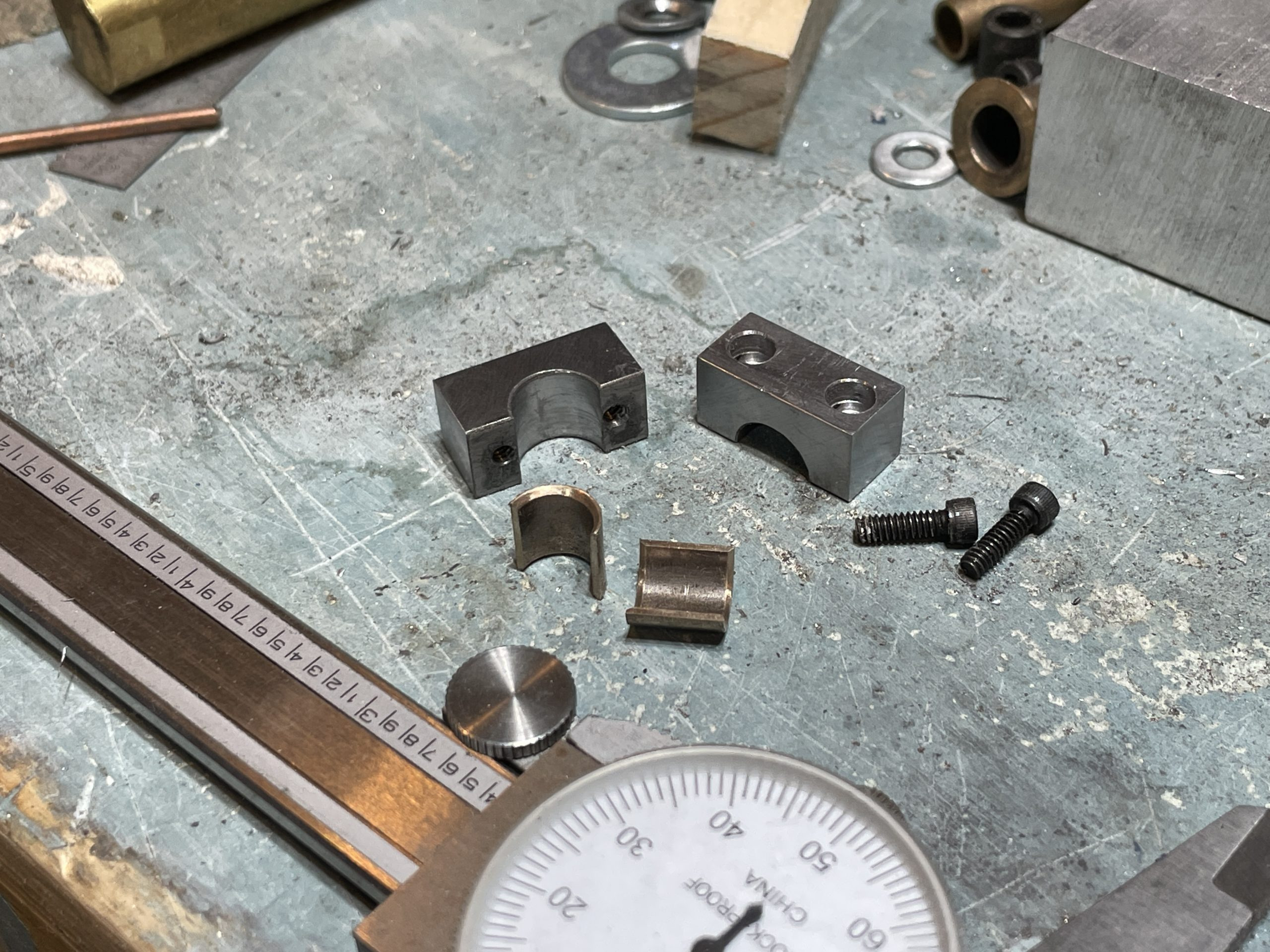
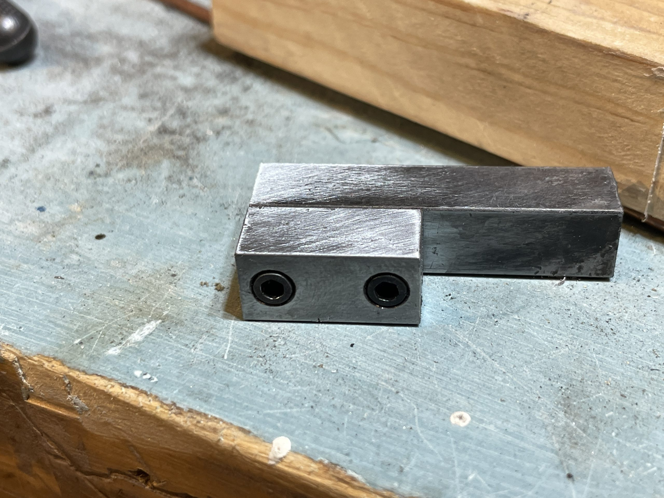
The final connectig rod end is square right now and you can see how the bearings fit in the hold in the picture below. There will be a large rod that is attached on the side that is sitting on the workbench in the photo an the end of that rod will have a tube that goes around the bearing on the big gear arms. The part as it is now is just one piece of the final conectig rod. You can’t see it here but I totally screwed up (by at least a few thousanths of an inch) when I tred to make the counterbores deeper so the screws would be more recessed. I masured them badly when I drilled them the second time and now they are a little out-of-round at the top and a little off-center near the bottom of the counterbores. None of these parts will move at more than a few RPM so their fit is not critical like it would be in an engine. I could make another part but I would need to make both sides of this part in order to get the bearig hold properly centered when the pieces are screwed together and I don’t relish tapping any more 4-40 holes for $4 screws. It took ten minutes per hole to get those tapped properly (because I wanted to avoid any possibility of breaking a tap in there).
This is where I am with the project today, May 17th, 2022. I hope to finish this connecting rod this week and then install and test it. The motor on the machine is no the 3RPM motor I intend to use so I need to get out the properl motor and wire it up for testing soon to.