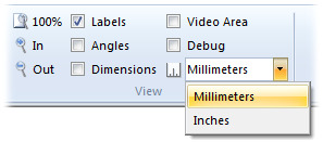
Even though I could have used arbitrary units of measurement for displaying dimensions of parts, that would not have allowed the user the ability to switch units without then enlarging or shrinking their mechanism to get that change. For instance, the user makes something that is 10.000 units wide and then decides that they want to switch from millimeters to inches. They would need to change the size of their mechanism to to the appropriate size in the new units and they would be responsible for knowing how to change things..
It would work to just show numbers that have no meaning to the software but it isn’t very attractive. So I have added units and the user can switch between them using a simple drop down list in the ribbon bar.
Units in the Ribbon Bar
The only units that I have so far are Inches and Millimeters. I don’t think that engineers ever use architectural units like Feet and any other metric values can be converted to mm quite easily.
The unit name is only displayed in the ribbon bar but it is saved with the mechanism and the program uses whatever is set in the mechanism when it is read from a file.
When a user has not started a drawing and the window is empty, I put in a rules in the upper left corner to show what scale things will appear when they are added in. This is useful to get to the right zoom level for the window before adding parts.
The Rules in an Empty Window
The rules adjusts itself to look good and to show a reasonable set of values. I am not sure if I should center this or just leave it in the corner.
Next Feature
I am thinking about adding a border like on most engineering drawings. This would be for adding name, date, project, and other information, to the mechanism drawing. It would be interesting, and more importantly, look cool. I’m not sure though if this is useful at all. Maybe working with cams and things of that sort would be better.


