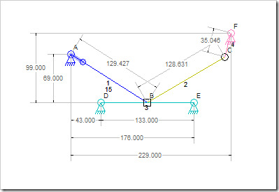
I am making good progress on the measurement/dimensions code for the Linkage program.
All Things Measured
The measurement feature is fully automatic. Enabling this by checking the Dimensions check box in the toolbar shows the measurements.
Things that are noteworthy at the moment
Anchor measurements are based on the leftmost anchor and the bottommost anchor. This means that there is a 0,0 (zero,zero) point in the mechanism for the ground anchors which is not always on one of the anchors. I did this because the anchors might be related to some real world object or fixture and this was the only way that made sense to display these. If there are just two anchors, there will also be a diagonal measurement shown.
Links with three connectors (not show in the picture above) will have their measurements shown based on the pair of connectors that have the most distance between them. This older post has the most clear picture of this feature. This allows the measurements to be used in a drill press or mill when making the parts. Essentially, there is a connector used as the 0,0 location for all others. This is slightly different from the anchors.
The units are essentially pixels at the moment but only because of the internal implementation. At various zoom levels, the numbers do not really relate to any specific unit or screen size information. I will be adding scaling later that will let a person pick how to show these numbers.
Dragging is the only way to specify a location, still.
The measurement are shown during simulation. This may be something I need to change since the measurements are useless while the mechanism is moving. It looks neat when they move, especially when there are a lot of measurements shown.
This is a work-in-progress so I am still trying to figure out how best to finish this feature. Other than scaling, I don’t know yet if there is anything I need to deal with. Some ideas are:
Let user click on a measurement to then enter a new value. I’m not sure how to handle this since other measurements might then change.
Let a user enter an x,y location for a connector.
Let a user pick the 0,0 location of the entire mechanism for then entering x,y coordinates.
Hide measurements during simulation.
Let a user pick any pair of connectors and display a measurement even if the connectors are not on the same link.
Allow a circle to be shown with one connector as the center and another as the position that defines the radius and then show the radius.
Let a user pick three connectors to then show the angle at the middle (second selected) connector.
I have a few people using this program for various projects. I hope that an email with a link to this post will help me get some input on what to do next.
One thing I have avoided is having the user pick exactly what to measure. The fully automated way of doing this has some shortcomings but I think that the simplicity of it outweighs the complexity of picking things manually. CAD program even let the user position the numeric information. they may even get to pick some aspects of the style of the drawings. As a fun at-home project, I just don’t have the time to write all of the code to keep track of things that way. Plus, when things start to move, all that selection of positions goes out the window!

