The fastening feature of the Linkage program is at bit of a kludge. Or maybe not. But it is weird in my mind. The user can create a mechanism and then draw some things on the drawing layer. These drawing elements are very simplistic and still get the job done for adding annotation to a machine. Where things got a little weird is when I added the fasten feature so that a drawing element could be attached to a mechanism element. Hmmm, why didn’t I use the word “attach” for this? Probably because implied something more sinister than merely moving one thing when another moves.
The big flaw that I had in the fasten feature was that the “unfasten” action was not consistent with the “split” action. When a connector connects two links, they can be disconnected from each other using the split feature. To unfasten, a user would simply select the items to unfasten and then fasten them… to nothing. Yep, it’s just not consistent.
Gears
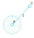
The gear above (the dotted circle) is rotating around connector B, as is link 2. But link 2 is not going to get moved because of that connection; only rotating input anchors cause all links to rotate around them. Since I might want to have the gear and the link to move together, I decided to use the fasten feature for this too (in addition to using it for drawing elements). It’s makes things more complicated, but I can’t figure out a simpler way to do this. I could have let users add more connectors to gears, since they are just links with a special “gear” property about them, but that is too restrictive and would make two gears fastened to a link too difficult to design.
Unfasten
Now that I use the fasten feature to fasten gears to links in the same way that drawing elements can be fastened to links, I will be adding an Unfasten button. This will greatly simplify the task of unfastening things.
I will also be adding some fasten information to the properties box so that the fastening can be “seen” somewhere. Right now, it’s invisible.

