
In some blog posts, and in a few emails to colleagues and customers, I have mentioned the term “architecture.” I’m not sure if most non-programmers understand the issues surrounding software architecture. But I sure do.
The Linkage program is familiar to people who read my blog (all 10 of them). Writing the Linkage program started at least 16 years ago and I knew nothing about mechanism design at that time. I still don’t. But I also knew, and know, nothing about how others write their simulators. In the following few paragraphs, I will describe the architecture of the Linkage source code and how the architectural choices have given me headaches.
Document–View Architecture
The Linkage program is written in C++ using MFC, a set of C++ classes from Microsoft that help people write Windows programs more easily. MFC is an older technology from WPF, WinRT, WinForms, and others. But for a straight Win32 (which includes support for 64 bit operations and is just stuck with that name), MFC is a good way to go for single-platform development. MFC supports a document-view architecture where information about what’s in a document is separate from the code and information about how to draw the document. The Linkage program considers the information about the positions of links and connectors, how they relate to each other, and the various properties of them, as being the document. And since the position in the window and zoom information of the screen image is stored with the other data, it too is part of the document. All of the code for drawing the images in the screen, in image files, in video files, and printing, is all part of the view.
The benefits to the document-view architecture is that modifications to the view source code won’t break any code for the document. This holds true as long as the public parts of the view and the document don’t change. If I were to add a new type of element to the mechanism structure to hold something that is not a link or connector, lots of code will get changed. But if I change the document to get saved in some proprietary format instead of as XML data, then only the document is affected by this and no other code will know or care about the change.
This document-view architecture is one design decision that seems to be working fairly well and is a good example of what software architecture is all about.
Document
The document has a fairly reasonable architecture, minus some issues that I will discuss later. The document has the code that keeps track of links and connectors, and the other things that get written out to files. When the editor moves connectors around, or does other things that alter the document, the document is simply told what to do and it makes the change to its data.
View
The view is an interesting architectural issue because the view needs to know how to draw the document. The view code needs to get the list of connectors, the list of links, and other information, all from the document. The view knows as much about the document as the document knows about itself, minus the information about the actual file format. This is somewhat reasonable but like everything architectural in software, it seems like there could be a better way.
Simulator
The simulator code is not as cleanly designed as the document-view architecture or the document. I have separate C++ object classes for links and connectors, and the simulation code for moving links is actually part of the link object code. After all, a link knows about connectors anyhow, so why not keep code that moves links and connectors there in the link class? Well, because it makes the link class a bit heavy. Some other code that just handles the simulation should handle the simulation. Also, the operations that examine each link to see if it needs to be moved, is in the document code. The simulator is one place where I may make drastic changes to the code to put all of the simulation into a single code module.
But wait, there’s more. The simulator has a sort of architectural problem that goes beyond just keeping information in one place hidden from all others. It has more of an algorithm problem. This problem stems from my guessing at how to simulate a mechanism 16 years ago and persists today. This algorithm problem is the most serious design problem in all of the code and deserves its own heading…
Simulator Algorithm
The simulator algorithm does essentially one operation. And yes, I have written about this many times before; the algorithm finds two links that share a connector and each has some other connector that is in a known position for the simulation. The two links are then rotated so that they connect at the proper location. Think of it as taking two pieces of wood that each are screwed to the floor with a hinge. You move the two pieces until the ends of them are touching each other and then you screw them together. This is how the simulator works. it is quick and easy and takes minimal mathematics to perform.
But the flaw in this algorithm, this system of connecting links, is that there is no way to handle a link that has three other links connecting it to the rest of the mechanism. There are no two links that can be positions without knowing the position of at least one other. The Stephenson valve gear is a good example of this.

Stephenson Valve Gear

Linkage Stephenson Valve Gear (Not Quite Right Though)
Because of the simplicity of the simulation algorithm, other things that are not like the Stephenson valve gear also cannot be simulated. It won’t work because of the three connections going to that sliding connection link in the middle of it all. Ignore that I drew the rest of this incorrectly and should have used sliding connections on the right side rod that goes to the valves; it’s the three connection link in the middle that can never be simulated using my code. Another example would be just two links that are connected to each other with two connectors. This configuration could keep the simulator from running because the simulator treats each like a separate link even though they would act as one in the real world.

Two Links as One
And the final mechanism that cannot be simulated is the actuator triangle. If there are two links connected to each other on one end and then connected through an actuator on the other, they form a triangle. But like the situation above, that triangle is not treated like a single unified link for the simulator even though in the real world the actuator defines the third side of a triangle. My simulator can’t determine the shape of that triangle separate from the rest of the mechanism, and it then can’t use that triangle like it is one large link for the rest of the simulation.
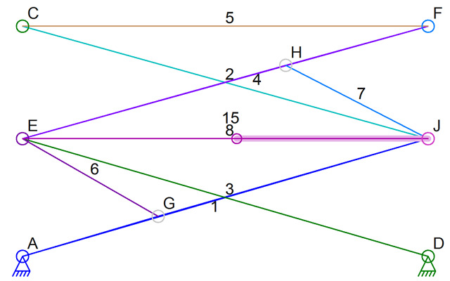
Actuator Triangles EHJ and EGJ
The reason why I include the simulator problems in a post about software architecture is that the architecture of the document doesn’t lend itself to solving the simulator problems. The mechanism could be made into some sort of tree structure (internally, not visibly), and any two links connected together to act as one link could be stored internally as one link that are only treated as two visibly. Any actuator triangle could be stored as a single link drawn as three, and which could be simulated to determine the link shape during the simulation. But again, the architecture of the document, connectors, and links, doesn’t give me that ability.
And maybe it shouldn’t. Maybe this extra layer of links, parent of multiple child links, should be temporary structures that exist only in the simulator code and only during simulation.
Changes
I may change the code to move any reference to the simulation out of the document object class and out of the link object class. A new simulator class would be better. A simulator object could then get created or initialized when the simulation starts, and it could keep track of special links that are parents of multiple “real” links within the document.
Or I could just change the entire simulator to use simultaneous equations for the simulation and calculate the positions of all connectors at the same time using math that is light-years past what I know about mathematics right now.
It is unclear if I should make any changes at all, because only a few people have every wanted to design a Stephenson valve gear or make actuator triangles with my software. But still, I would like to do at least a little better job of supporting those features sometime in the future.
By the way, there is a way to change the Stephenson valve gear to run in the simulator. I am not 100% sure if this has the same movement as the typical Stephenson valve gear because of the change in where link 8 connects. But I have seen this sort of connection on a real steam engine online, so maybe it’s okay. Having link 8 connect to E means that there are no longer 3 connections defining the location of link 2.
