Manufacturing has begun on ball lifter #2.
Design Animation of Lifter #2
The lower mechanism lifts the ball off the entry track to a position where link 3 at connector F can catch it. From there, it is lifted and dropped onto a short track about half way up the mechanism. The top of the mechanism is rotated 90 degrees in this video and in the plans because my Linkage software does not do 3D. Up at the top, the giant circle on the left (overlapping the other giant circle) is the path of a link that swoops down and picks up the ball off that holding track. But again, that rotation is 90 degrees off from what you see in the video. Maybe I should have just draw this as two separate plans next to each other.
The tiny lift at the bottom is just to get the ball to a point above another ball on the entry track. Otherwise it could not be picked up without pushing that second ball out of the way.
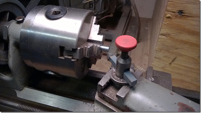
Cutting Spacers to Length
I used the lathe to trim the spacers to the right length. This is an improvement over the hand filing that I did on the parts on the previous lifter. These spacers also act as the hinge pin for some of the moving links.
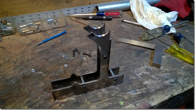
The Lower Frame
The Lower Frame
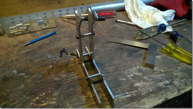
The lower frame is also the entry track for the balls. The curved part at the top is where the ball will sit after being dropped off by the lower mechanism. The upper frame, that also reaches the table behind this lower frame, will be rotated 90 degrees from these parts and the two sections will screw together.
I’m not sure how to make the holding track at the top of this. The rails need to go side-to-side and hold the ball up high enough that these frame parts don’t get in the way.
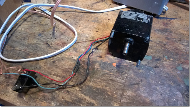
Gear Head Motor
The final part that I have right now is the motor. I had to completely clean and grease the gear box and make a minor repair to one of the gears teeth. It works well now for a motor that cost a few bucks on eBay.
Work continues…


