

I did some work this week on the cam feature for the Linkage program. Cams are found in many places including in car engines – they open and close the valves – and in many industrial machines. Car engine cams are all based on a similar shape and have essentially a single lobe (bump). The Linkage program is not going to have single-lobe cams because the Linkage program isn’t for engine design. Instead, the cams will be designed using a polyline. A polyline is essentially a set of segments strung together end-to-end. The word “line” doesn’t mean that the segments are straight although they can be. The curves in the Linkage program will be quadratic bezier curves. Once the feature is fully implemented, the polylines will be used for defining the shape of cams as well as for defining the outside decorative shape of links. I have had the polylines loading, saving, stretching, and rotating, in the software for a long time but editing them has not been working. That’s what I worked on this week and it’s a hard thing to implement.
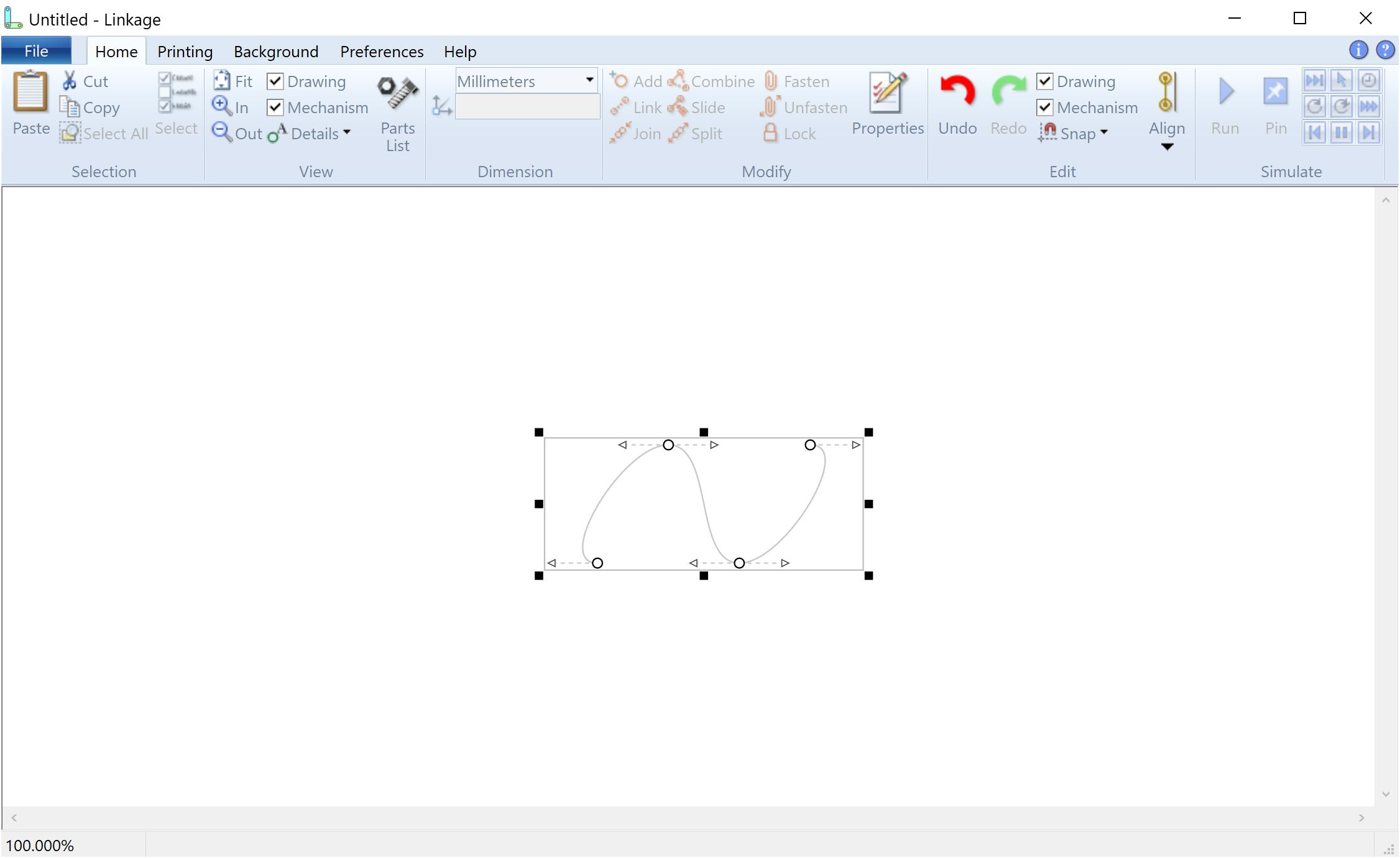
When a polyline is dropped into the mechanism, it appears with the shape in the image above. There are three visible segments and the fourth closing segment can be displayed by changing the polyline properties to make it a “closed” polyline. There are four nodes and each is smooth and symmetrical. As I said, this can be saved in a file and it opens properly. This can be stretched and rotated using the control knobs.
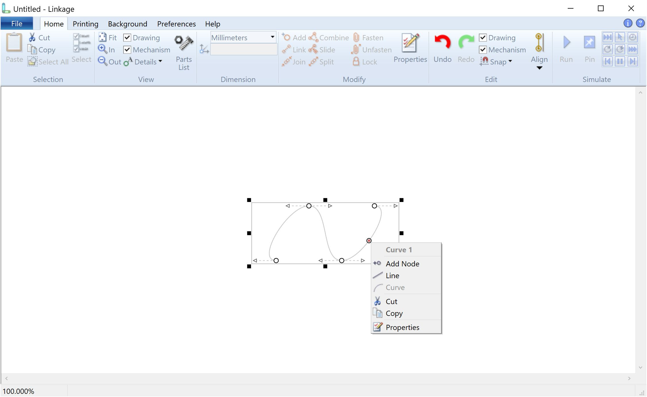
When the right mouse button is used to click on a segment of the polyline, I now have a popup menu working. This was one of the most troublesome features that I’ve worked on in a while because the Microsoft controls are rather complicated and devious. For instance, I had to do some special work to make the name of the segment show up a the top of the menu, and making it bold and grey took hours to get working. The more difficult task was getting the icons to show on each item because the “cut”, etc., somehow uses the icon that is set in the toolbar for those same functions and there is no way to set the icon at the time the menu is created. Since the toolbar doesn’t have “Add Node” and other similar functions, I had to figure out how to add a hidden panel to the toolbar and then add those functions into that panel. Microsoft was nice enough to support a flag for hiding the panel but not nice enough to make that flag accessible from my code. I managed to get access to it in a rather sneaky way but again, it took hours to find the flag since there is no documentation for a lot of their older C++ features.
You can see in that picture with the menu that there is a circle and red dot near the menu. That is where I right-clicked. I had to work on my geometry library to find that point even when the mouse pointer is not quite on the curve.
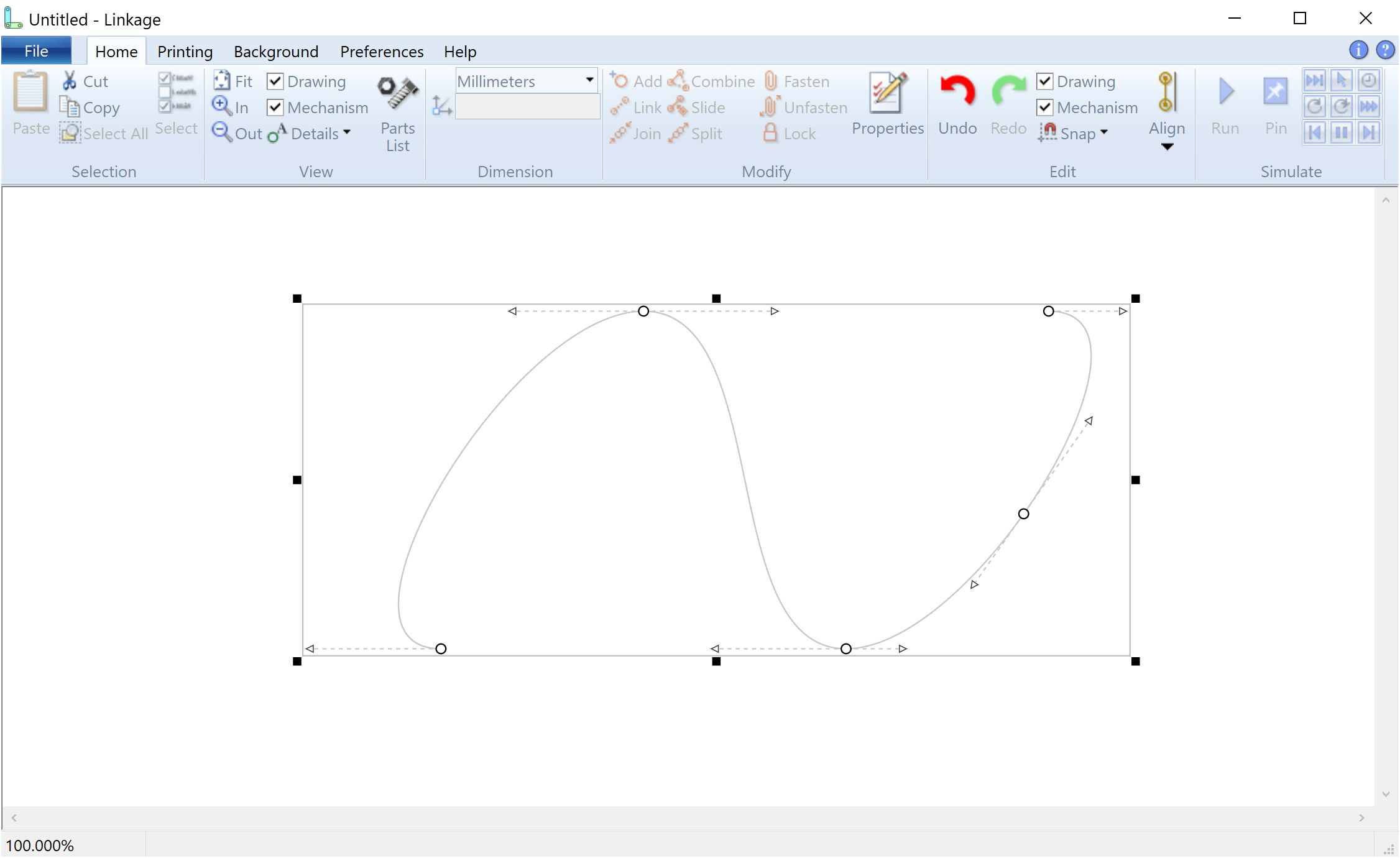
After clicking selecting the “Add Node” menu item and zooming in a bit, you can see the resulting split curve. This was the most fun and interesting part of the work in the last few days and I was up until 4am working on it last night. I read a few web pages about bezier curves but ultimately had to figure out the mechanism to do this curve splitting. The pages did lead me on the right path although the way these curves work, I might have been able to figure it out completely alone. Check out his demonstration of a Bezier curve being drawn.
A few intersting things showed up that I didn’t think about before writing the splitting code. The new node as well as the node before adn after the split cannot be symmetrical. Symmetrical nodes have control points that are equidistant from the node on either side of it. This symmetrical-or-not-symmetrical thing is a feature of the polyline and the Bezier curve itself is not affected by it. It was just interesting that all of the control points of the Bezier curve, as well as the new control points of the resulting two curves, are all in new positions.
I should admit right now that I did have a few bugs that caused me quite some time to fix and that I am more often plagued by typos then I was ten years ago. I think my programming design skills are better than before but my ability to write clean code that works is getting a little weaker.
So that’s it. I still can’t drag those nodes or control points to change the curve shape but I can at least add a node. I’ll work on a few other aspects of this, like being able to change a curve into a line, and then get back to the actual node dragging after I make some progress. The node dragging required a lot of work a year ago and I sort of lost interested before it was done. The ability to even have more than one control knob (nodes and control points) on an element was not in the software until I started work on the cams and it was tricky to get working.
I’ll post more when I have some more cam features working.