With gears somewhat working in the Linkage program (there is a small glitch to fix still), I need to figure out what to do next. I have a list of user requests as well as a list of things that I want. I’m not sure what to do yet.
Cams
With gears working, I can use some of that code to also implement cams. Mostly, the gear fastening to links feature is what make the cams more easily implemented. I was never sure in the past how to have cams and links moving together.
I have already played around with cam shapes. My geometric constructions page has some experiments in cam design that I implemented in JavaScript.
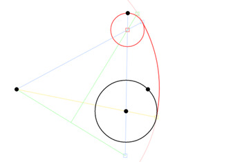
Part of An Engine Valve Cam
The cam lobe in the image above is a common design using a radius for the heel, a radius for the flank, and a radius for the nose. the flank can also be straight. I didn’t draw the left flank, only the right. The shape is calculated from the center point, the radius of the heel circle, the radius of the flank, and the end of the nose. Oh, and the position of the nose point relative to the position of the flank radius center. The nose radius is computed from the other values.
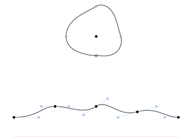
I also tried Bezier curves to define the shape of the cam. This is what a toy-maker might use.
Bezier Cam
The Bezier cam has four curves. The start point and end point are the same point in the bottom set of curves. Adjusting the shape of the curves at the bottom adjusts the shape of the lobe above it. I would eventually use just the cam lobe alone to display and adjust the shape, but in this experiment, it was easier to transfer the curves from the normal Bezier curve representation to the polar coordinates of the cam lobe.
Parts List
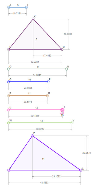
One idea that I’ve been thinking of for a year or two has been to display all of the parts of a mechanism separately. This would be a display option that would disable editing of the parts and would then display each link separately in a column. I would also rotate the parts to take up the most room horizontally and the least room vertically, since they would be stacked on above the other on screen and when printed.
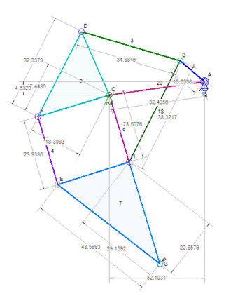
Mechanism View
Parts View
The parts view above is an approximation of what the program would really display. I simply copied the parts from the mechanism above that and then rotated and aligned them to look like this. Since I faked this, the colors and labels don’t match between the mechanism and parts views. I think that this would be an important addition to the program since reading full-size printouts is difficult when lots parts overlap.
The only hard part of this is deciding what part of the code will handle this. I keep track of the mechanism in one piece of code but a completely different part of the code handles the view. Things are not as separate as they should be because the size of the connector circles, and things of that sort, don’t change when zooming in and out; they are part of the display and therefore don’t actually affect the size of the mechanism. It’s all a bit tricky. This new feature would just make the code that much more complex, but might help because I could then include the dimension lines when calculating the visual size of the mechanism.
Constraints
I think that this is the correct word for this feature. Users should be able to constrain or “lock” a link so that it cannot have its size or shape changed. I have been reluctant to work on this feature because I don’t know how to deal with it in the editor; What happens if a user has a link constrained/locked and then tried to move one of the connectors? Do they all move? Can the link be rotated (which can change the size of the link because of math rounding issues), or is it really suck at one size with no alterations allowed?
And then what happens if a link is connected to another that is constrained and one of the connectors is moved? Do both links move together? I think that would be the appropriate solution. Essentially, selecting a connector or a link that is part of a constrained link makes all connectors and links that are connected to it be selected too. The selection doesn’t need to be visible, but some sort of indication would be a great idea.
Summary
Those are the ideas that I have at the moment for major changes to the Linkage program. I think that cams will be the last big change because I need to come up with a user interface for changing the cam shapes. That might mean adding an editing mode selection or adding a new window to edit one cam at a time separate form the mechanism. I could make it work like the control knob on the linear actuators, which is only visible and moveable when the actuator is selected. That is a really good modeless option for editing cam shapes.


I meant to ask about worm and worm-wheel…A rack n pinion won’t need a Z-depth representation.
I think that I’ll have to write all of the code from scratch pretty soon. The simple gears were quite a difficult feature to fit into the existing internal architecture. But I think that Worm gears would just not work in a 2D world.
I recently had to design a 3D mechanism and it was tough. The biggest problem was that I have one set of links on a plane and then another set on a plane 90 degrees off from that. I drew both from their own 2D point-of-view and then did a little work by hand to resolve the connection between them. I haven’t built the mechanism yet so I don’t know if I got it right or not.
The Bezier cam looked like such an obvious solution to designing cams for toys. I’m glad that someone liked it.
The only problem I have not even though about addressing is how the cam shape and the follower position don’t match if the follower is on a pivot arm. The 2D side view of the Bezier curve only shows the cam shape but not the actual position of the follower over time. It’s all because the follower will proceed or recede as the cam goes around depending on its position. The cam follower would move up and down relative to the cam in a curve, not a straight line!
Anyhow, sorry for the long wait. I’ll try to post something when I can get around to writing some code for this.
Dave
Hi,
I agree about the difficulty of spatial arrangements in a 2d platform. I am not anywhere even close to any kind of coding, but I was thinking that the follower mechanism could be based on something like the sliding joint, or something on the lines of what you have done for the ‘actuator’. If I am not wrong, the problem is to get the follower to synchronize with the way the bezier is manipulated. As in, for it to be in contact with the cam profile and also displace accordingly. For a pivoted follower, a fixed anchor and a link would work? Same for a rack and pinion? Again I am just guessing..
Keeping aside all of this, I have been trying out MechDesigner. The linkage is built in the mechanism first and then the software calculates the cam profile for it. As I change the linkage parameters, the cam profile updates accordingly. Also, I am trying to figure out Silux 2.0, but it has such a round-about way to get things working. Your software wins hands down when it comes to simplicity of operations and the cleanest interface I have come across. Congratulations for that.
Thanks. That was the main goal. I wanted to make it as easy as using a drawing program. CAD programs are too hard for me to ever want to use.
Hi,
When I connect two gears (driver on a rotating anchor and other using a normal link) and set a gear ratio, the smaller gear does revolve like a planetary gear but doesn’t seem to rotate as it goes around the driver gear. Is it meant to be like that? or they aren’t behaving like planetary gears at all?
The gear that is connected to the rotating anchor is rotating because of the anchor rotation. If you want it to stand still, you will need another anchor nearby. Click on the gear and the anchor and then hit the “fasten” button.
I’ll send you and email and you can reply to it with your .linkage2 file attached. Then I can quickly see if I am misunderstanding the problem.
I faced a serious user-interface dilemma when working with gears that are on rotating anchors. The problem is how to make the gear rotate when desired, but to then not rotate and be “fixed” at other times. Instead of adding a property to the gear, to rotate or not, I opted to use the fastening mechanism to fasten the gear to another anchor, thus keeping it from rotating.
I’m open to suggestions on how to make this more easily understood.
I disliked the idea of having a property that is only valid in certain situations. For a gear that is not on a rotating anchor, a “don’t rotate” option would have to be disabled. But maybe that’s a better idea than fastening the gear to another anchor.
Dave
I think the bezier cam is just brilliant! I am imagining converting animation walk cycles directly into cam-follower mechanism..Also I was wondering about the possibility of a rack and pinion, although the constraint would be to deal with the Z depth in a 2d package..Also, any thoughts on internal gears? Anyway I will be more than thrilled to get the cams working…can’t get too greedy…cheers!
speck
Hello Dave,
First and foremost thank you for developing such an intelligent yet simplified software. Just downloaded it and I love it already. Its just the thing I was looking for. I am just a rookie in the kinetic mechanism space and Linkage seems to answer all my questions! Thanks again…
Waiting impatiently for the Cams to be introduced.
I too would like to get cams working. I have had far less time to work on this than I would like.
Thanks for your interest. Besides cams, if you have any other requests or ideas, feel free to let me know. Development is slow at the moment but I might get some time to work on this soon.
Dave