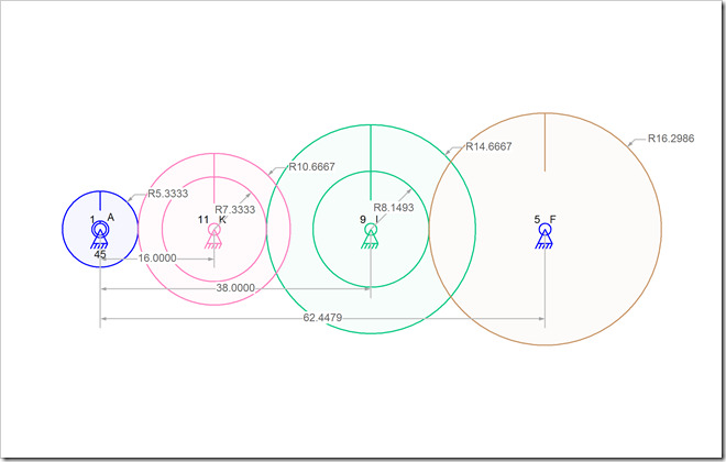
I am changing the way radii are drawn in the Linkage program. The old way was to show the radius value inside of the circle but that doesn’t seem typical, at least not in the U.S.
New Radius Value Position
The new way draws the radius value outside of the circle with a bent line and arrow pointing to the circle.
In the case of gears where there are multiple circles on the same center-point, I draw the smaller circles with their radius values inside, like before. This helps to avoid overlapping radius values (and it looks neat too).
This change will be in the next version 3 beta. I see lots of hits on the download page, but no one has sent me any email about bugs. I can only assume that no one cares about the gears, or doesn’t care enough to report any problems. let’s hope that the bugs are minimal, now that I’ve found and fixed a few.
I am considering a change to the auto-dimensioning feature. Since I don’t think that I can create the parts list view of the mechanism anytime soon, a selective dimensioning feature would be almost as good. I know that sometimes mechanisms are too cluttered to read the dimensions. At least being able to turn off the auto-dimensions for the drawing layer or for selected links and connectors, printouts might be easier to work from.

