The Linkage program lets the user add linear actuators to a mechanism. These are drawn a little bit like a hydraulic cylinder or a similar motorized linear actuator.
Simple Linear Actuator
There is an interesting issue with these actuators. Actually, there is a bug in how the actuator is drawn as well as a design issue.
First, the design issue is related to the physical nature of a hydraulic cylinder unit. The movement of a hydraulic unit cannot be longer than the cylinder portion of the unit. You just can’t stick a two foot long piston into a one foot long cylinder and get two feet of movement. In this case, the one foot length of the cylinder is the limiting length. The dilemma is that there may be a type of linear actuator available that does allow a full two feet of movement in a unit that is only two feet long. How should I draw these things to look good while also allowing any length of movement?
Fortunately, this problem only shows up with initially long linear actuators.
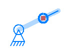
Actuator That Shrinks Initially
You can see in the above picture that the actuator will get shorter and that it will look odd once the end connector moves to a point where it is shorter than the overall throw of the unit. I just don’t know if I should make this impossible by limiting the throw length.
The pother issue is a bug in the code that lets the overall length of the linear actuator be shorter than the throw length. The shaded “cylinder” part of the unit is drawn it’s expected length but the circle used for dragging that “cylinder” or throw length is moved to never be past the end connector.
Strange Linear Actuator Drawing
New User
I received an email today from another person trying to use the Linkage Designer and Simulator. This is cool and I was able to instruct him on how to create sliding connectors. I’m a little surprised that someone is using this and more surprised that they are using sliding connectors. I hope that I can get some good feedback about what works well and what is tricky to do with this program. Either that or learn about some new type of connection or mechanism that I might support in future versions.
This user had trouble creating a sliding mechanism. The instructions are not very clear and I went ahead and added a tiny bit of text to the users guide to at least hint about how to do it.
Instructions for Creating a Simple Sliding Mechanism
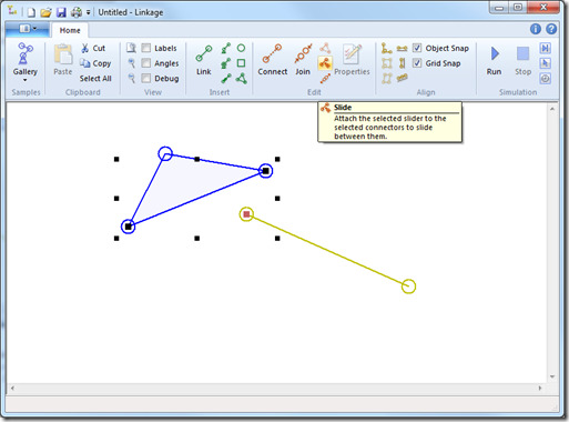
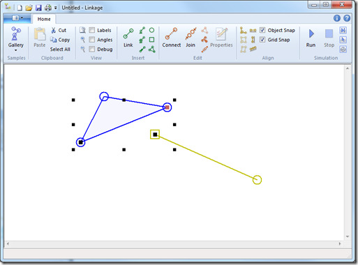
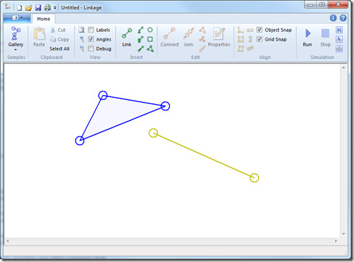 1. Create enough of a mechanism so that there is a link with two connectors and then one other connector that is alone or part of some other link. The picture above shows a good starting point.
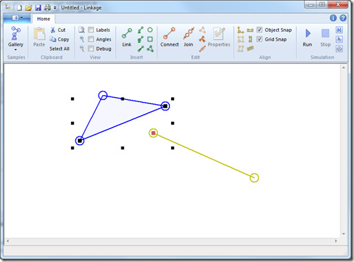 2. Select the “other” connector that will slide back and forth then select the two connectors that are going to be the limits to the sliding and that define the line that the sliding connector will follow. The first selected connector has a red selection square in it and the others are black. Do not select any links, only connectors.
Notice that the Slide function is available in the tool bar. If the selected connectors cannot be attached properly to make a sliding connector mechanism then this function would not be available.
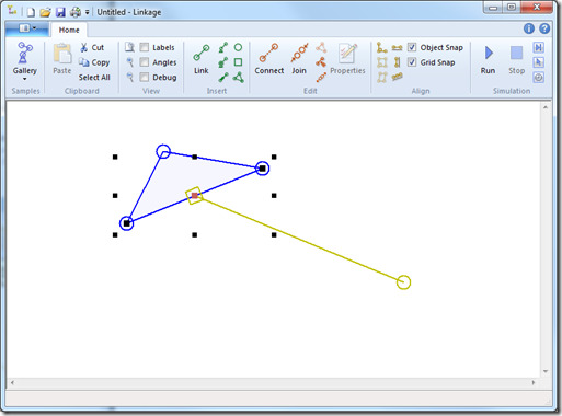
3. Click on the Slide icon. Notice that the “other” connector was converted to a sliding connector and then it was attached to the line between the other two connectors. The sliding connector is now limited so that it can only be moved on that line.
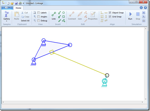
4. Finish creating a working mechanism. Notice that the triangle link was anchored in two places and it will never move.
Below is a video of this mechanism running. Numerous examples of sliding mechanisms are available in the sample gallery within the Linkage program.
It is also possible to start with one sliding connector.
In the picture above, there is one sliding connector but it has not been attached or connected to anything else. When selecting three connectors and one is a sliding connector, the slide function is available and the sliding connector does not need to be the first one selected.

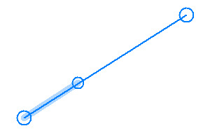
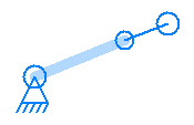
It’s handy having a longer throw length as it helps simulate the function trunnion mounted cylinders where the cylinder side is pinned along the cylinder body. Visually it doesn’t look right but is still functions in the model. Have a look and see what you can make of it. It would be handy to have it visually correct too.
Telescopic rams is another example of stroke length being different to standard, mainly used in tipping trailers.
Cheers,
I’m looking at photos of trunnion-mounted cylinders right now and I’m glad that the software works for those, even if by accident. I’ll see if it’s easy to at least draw the “cylinder” more accurately. Thanks for mentioning all of this – I hadn’t paid much attention to the different types of actuators out in the real work beyond the typical hydraulics and electric actuators that have a throw shorter than their body length.