

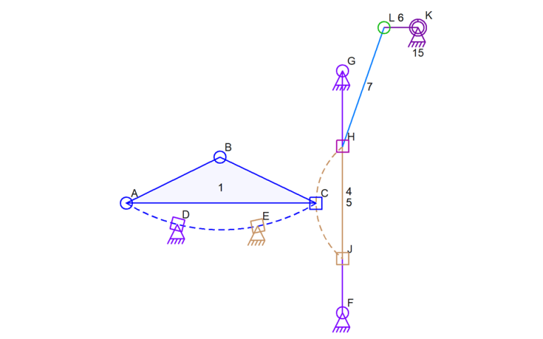
With the mechanism in the image, there are three sliding connectors affecting link 1 (on the left). This is an interesting mechanism to simulate. In this situations, the calculations are easy because D and E both have the same slide radius. With the same slide radius, we can calculate the center point of rotation for that entire link and find the circle that defines where C could be placed. Finding the intersection of the circle of possibilities for connector C and the circle defined by the connector C radius lets the code then know where connector C should be positioned.
Note that the above calculations rely on link 5, the link with sliders H and J already being in a final position. The data will always be structured correctly to calculation link 5 before link 1 so that won’t ever go wrong.
This situation has some difficulties. They are mostly related the sliding connectors D and E and how they could just be ground anchors with some new sliders on link 1 sliding on a path between them. The functionality is identical and the code needs to be able to figure this out and see that it’s identical.
The final interesting thing about this is the possibility that D and E have different slide radii (radiuses?). If that’s the case then I don’t see there being an equation or set of equations to solve it. This would be one of those situations that needs an iterative algorithm where link 1 is moved along it’s path from one end to the other while the code checks to see when connector C crosses it’s slide path. I do this sort of iterative calculation for intersecting lines and circles with splines because splines also don’t have a single equation to define their shape.
If you missed posts about the way the data is structured for the simulator, here’s a quite review: The links start out in a list and the code reads through that list looking for subsets of links whose shape, related to just each other, can be calculated. Three static (not actuators) links that form a triangular structure meet that requirement. When a structure of found, a new compound link is created with the component links as children. The compound link will look to the code like a link that has all of the connectors of the child links. Later when the simulator is running, the compound link is processed and it’s shape it determined by the children. That then causes the shape of the compound link to be know and it can be used to calculate the shape of other parts of the mechanism, most likely parent compound links. Other types of compound links exist that are not triangles. For instance, the ground and a link that have motor connector between then only has two links, but the shape of the combination of the two is easily calculated using the angle of the motor based on the time since the simulation started. Once the calculation is complete, the parent compound link can be used to calculate the shape of a parent compound link. So in the case of the mechanism above, the motor and it’s links, and the position of link 5, all get calculated before the sliding link 1 is ever worked on due to the tree structure and how it’s created.