
 Note that this tutorial requires a yet-to-be-released version of the Linkage program. If you really want a copy, I can send you the executable file. But it won’t have a digital signature due to me being lazy and just now taking steps to get a new code signing certificate after the old one expired. The only new feature that is needed is the guidelines feature. It’s possible to manually position one of the connectors and get very close to accurate results; the steps to do that are described in the tutorial when the time comes to do that. There may also be a mathematical way to calculate the position of that connector. If you figure it out, let me know.
Hoberman Sphere
The Hoberman Sphere is a mechanism designed by the legendary Chuck Hoberman. It is pretty much the mechanism of a scissor lift but in a circle that is then repeated, sort of, into a sphere.
I don’t know what the mechanism is called if just created in 2D. Also, in 2D, there is no need for clever connections between more than 2 links in 3D space like there is in the 3D sphere mechanism. The Hoberman Sphere toy has the connections between some links as two connections to a small intermediate link. Since this is 2D, the mechanism is quite simple.
Tutorial
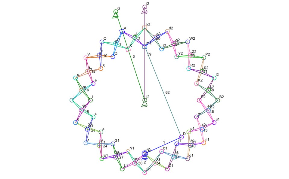
Here is the finished mechanism. There is a “motor” added to move the parts in this picture:

Finished Mechanism
To create this, first create a vertically oriented link with two anchors. You should already know how to do this, but here’s how in case you missed an earlier lesson (self taught of course): if there is not already an anchor at the center of the Window, right click and then add an anchor. Right click and add another anchor above the first. Drag the second anchor until it snaps into position directly above the first. Select them both and then tap the “L” key or click the LINK button in the tool bar.

The First Link
Select just the link and then enter “9*” into the dimensions text box (without those quotes of course) in the tool bar and then hit the “enter” key. This rotates the link 9 degrees.

Rotated 9 Degrees
Make a copy of this link by selecting it and clicking CTRL-C and then CTRL-V (or by clicking the copy and then paste buttons in the tool bar). While the copy is still selected, type “-18*” to rotate this link 18 degrees in the opposite direction. Horizontal flipping would have worked just fine too.

Two Links
Drag the second link sideways until the bottom connector snaps to the position of the bottom connector of the first link. You now have a “V” shape.

V Shape
Select both of the bottom connectors, if they were not automatically joined together, and then click on the JOIN button in the tool bar or tap the “J” key. This causes the two connectors to become a single connector, thus connecting those links together. This joining of the bottom links is not absolutely necessary but it would be painful to select the correct connector in later operations if there were two of them at the same location.

Two Spokes
Drop in a triangle link up between the two previous links. I will call them “spokes” since the common connector at the bottom will be the center of the mechanism.

Dropped In Triangle Link
Select the center connector (the one shared by the two spoke links) and also select (using CTRL-click) the other end of a spoke up to the left. Then also select a connector on the new triangle link you dropped in. With three connectors selected, tap the “S” key or click on the SLIDE button in the tool bar. This creates a sliding connection and the connector on the triangle link will now be square and will slide along the left spoke link.

One Sliding Connection
Repeat the same process with the right spoke and one of the other connectors on the triangle link.

Two Sliding Connections
You now have two spokes and a triangle link with one connector sliding on the left spoke and another connector sliding on the right spoke.
Move the connectors of the triangle link into the position shown. These are just rough placements and don’t need to be exact.

Rough Triangle Link Position
Drop in a guideline. The guideline feature is a new Linkage feature that is not available before version 3.10. Drag the ends of the guideline so it is vertical and aligned through the common connector at the bottom of the mechanism (the center of the spokes).

Vertical Guideline Through Middle
Now the tricky part. First, drop in another guideline anywhere near the mechanism.

Select in this order: The left sliding connector of the triangle link, the lower end of the new guideline, and the right sliding connector of the triangle link.

Next, click on the ALIGN button in the tool bar to show the ALIGN menu and select the EVEN SPACING option. This will leave the first and last selected elements in their current positions and, in order, evenly space the other selected elements between them. This ends up centering the lower end of the new guideline between the two sliding connectors.

Align Menu – Even Space

Guideline End Centered
Now select the right side sliding connector, the now centered end of the guideline, and the other end of the guideline, all in that order. Use the ALIGN menu again and select the RIGHT ANGLE option. This will move the end of the guideline into position so that the three selected connectors/points form a right angle. The guideline is now perpendicular to the line between the sliding connectors and is centered between them. All versions of the Linkage program support the features that I have described so far.

Guideline Perpendicular to Sliding Connectors
Zoom in on the triangle link.

Zoomed In
You can see in the picture above that the perpendicular guideline crosses the vertical guideline. This intersection point is the critical point in the whole mechanism. You will be moving that pivot connector on the triangle link to be in that exact spot. Once there, no matter how the triangle link is slid along the two spokes, that pivot connector will follow the path defined by the vertical guideline.
If you prefer to use regular drawing lines using an older version of the Linkage program, and want to try to align the connector by eye, follow the next instructions in italics. Otherwise skip them.
Redo the part of the instructions that used guidelines and use drawing lines instead. The mechanism will look the same except for the color of the “guidelines” you are faking with drawing lines. Now drag the pivot connector on the triangle link as close as you can get it to the intersection of the two fake guidelines. Zoom in as far as you can and use the mouse and arrow keys to move that connector to it appears to be on that intersection point. Add another drawing line and make it parallel to the line between the two sliding connectors and drag it to cross that same point if that helps align the connector. To be more precise, select the entire mechanism (draw a selection box around it when zoomed out) and enlarge it 5000%. The do this manual adjustment and then select the mechanism and shrink it to 2%. Scaling can be done by selecting the entire mechanism and typing in the percentage values, along with the percent sign, into the dimension text box in the tool bar (and hitting the “enter” key). Scaling up before changing the location of the pivot connector is a way to be more precise about it.
If you skipped the alternate old method above, just drag the pivot connector on the triangle link to the intersection of the guidelines. When it is very close to that point, it will snap to that position.

Pivot Connector In Position
Now that the triangle link is the correct shape, select it and make a copy (copy and paste). The copy is selected when it is pasted in so open the ALIGN menu and selected the FLIP HORIZONTAL option.

Two Triangle Links
Now drag the new triangle link until the pivot connector snaps to the location of the pivot connector on the first triangle link. If the link snaps to weird positions, zoom in and try it – this helps keep the link from snapping to other close locations since those other locations are now further away on the screen.

Properly Aligned Triangle Links
The second to last of these complicated steps is to select both pivot connectors, by drawing a selection box around them, and joining them using the JOIN feature (“J” key or JOIN button).

One Pivot for Two Triangle Links
The next step is the last of these complicated steps. Follow the instructions in italics below if you are using an older version of the software. If you have version 3.10 or later, you can skip those steps.
The older Linkage software would move connectors when creating sliding connections. In this mechanism, the second triangle link has two connectors that are not sliding yet because the second triangle link was a copy of the first – copies do not inherit sliding connections to links that are not being copied too. Drop in a drawing point and drag it until it snaps into position on top of the upper-right connector of that second triangle link. Do the same thing with another drawing point, snapping it to the position of the lower-left connector on the second triangle link. This will save those locations for later.
using the new or the old software, select the bottom anchor and the top-right anchor of the right spoke. Also select the top-right connector on the second triangle link. With all three selected, tap the “S” key or click on the “SLIDE” button in the tool bar. The second triangle link now has its right-side sliding connector sliding on the right-side spoke.
If you are using the old software, drag the sliding connector so it snaps to the drawing point that was added earlier. Now it is in the right position.
Repeat this process of creating the sliding connection for the left side of the second triangle link.

Finished Triangle Links
The “motor” will get added now in order to test the triangle link connections. If the connectors were all positioned correctly and the triangle links and spokes are symmetrical around the center guideline, this should work as expected.
Drop in an anchor with a link. Place it below all of the other elements and close to centered under them.

“Motor” in Place
Select the connector on the end of the new link and also select the bottom right sliding connector of the triangle link. With both selected, create a link by tapping the “L” key or clicking on the “LINK” button in the tool bar.

Ready to Run
Tap the “R” key or click on the RUN button to see this running. Here is a video of the mechanism working so far:
It is interesting to note that one of the sliding connections is not necessary for this to work. The sliding connection above the slider that is linked to the motor can be a normal connector that is not connected to anything. Either that one or the connector to the left of the slider that is linked to the motor can be normal non-sliding connections. It takes just three sliders to completely define the mechanism and the movement.
Now to create the full circle…
Select the left spoke link and the two triangle links. Do a copy and then a paste.

Pasted Link on top of Existing Links
Do not de-select anything. Click on one of the triangle links to change from scale mode to rotate mode.

Ready to Rotate
Now click and drag the center marker until it snaps into position on top of the anchor that is at the bottom of the spokes. Not onto the bottom-most anchor in the mechanism since that is the motor. Click on the dimension text box in the tool bar and type “18*” and hit the “enter” key. This will rotate the selected elements 18 degrees around the center point.

Second Group
Copy while the rotated elements are still selected. Paste the copy into place and then, if using Linkage software prior to 3.10, click on one of the links to switch to centering mode and adjust the center point so it is back onto the center of the spokes. The 3.10 and later versions leave the rotation center where it was when pasting elements. After doing this enough times, you will have a complete circle.

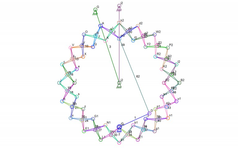
Full Circle
Note that most of the new sliding connectors are on top of others and show the little half-circle marker. The half-circle is an indicator that tells you two or more connectors are at the same location but are not just one connector. The last paste and rotate operation also made a copy of a spoke on top of another.
First, Select the extra spoke and delete it. This does turn two of the sliding connectors into regular pivot connectors. Then drag a small selection box around every sliding connector that overlaps another and do a JOIN operation (“J” key or JOIN button). When you get around to the connectors that were on that deleted extra spoke, do the same thing. Now each triangle link will be connected to another next to it.

Finished Hoberman “Wheel”
Run this and it should work. If you used older software then there is a very strong possibility that this won’t work. The manual placement of the connector between the two triangle links will certainly lead to a small error in the alignment of the parts and there will be binding. If this is happening, follow the steps below to get a working mechanism that is not quite aligned properly.
Select the last two triangle links that were copied. This will leave one missing set of triangle links. Now delete the spokes starting with the most recent spoke that was copied (before the extra one that was deleted).

Non-Binding Mechanism
Run the mechanism and it should work. If there is still a problem, select the sliding connector that is the lower-left-most sliding connector. Split it (SPLIT button) and that will leave it in the same location but it will no longer slide on the spoke. It’s fine to do this since it’s position is already dictated by the other triangle link and the connector that connects them. Now the mechanism should run. To get an idea about how much error there was because the first pivot connector was positioned by hand, copy the final two triangle links in the chain – the triangles just to the right of the first two triangle links created – and paste them. Then click on one of them again to change to rotation mode, drag the center to the center of the wheel, and type “18*” in the tool bar dimension text box and hit the “enter” key. Then JOIN the overlapping connectors on the right side just like earlier when the links were being copied and pasted in a circle. Do not JOIN the final two connectors since these will not line up properly when the simulation is running. Run the simulation and see that they don’t line up because of the repeated error with that manually positioned connectors.
Please contact me if you need help with any of these steps. I’ll be glad to help.
Dave