It took me a while but I now totally understand the DXF format. It wasn’t until I needed to change a bit of the output from the free source code I used, that I needed up getting the details I needed to not be confused. The format is stupid simple except for the oddball aspect of tagging things with numbers instead of labels. But then numbers take up less space… except for the X coordinate of a point that is tagged with number 10 instead of the letter X.
The code that I found that was free was really weird. I had to port it from C# to C++ and discovered some really strange concepts used by the original author. He would use an array of strings but then in each string in the array, there would be multiple pieces of data separated by vertical bar characters. Then before using the array of strings, the code would combine them into a single large string with, wait for it, vertical bar characters between the pieces from the array. Why not just concatenate all of the string literals into a single string in the first place:
string Temp;
Temp = “0|CIRCLE|”;
Temp += “10|2.5|20|45.1|30|0|”;
return Temp;
The original code did something like the code below for no apparent reason.
string Temp[];
Temp[0] = “0|CIRCLE”;
Temp[1] = “10|2.5|20|45.1|30|0”;
string NewString = CombineArrayEntries( Temp, Temp.Count(), '|' );
return NewString;
You can see that there is an extra line of code, really a few lines in the original sources since I am writing pseudo code above, that are just not needed.
This avoids the step of combining the strings in the array into a single large string. Maybe it’s less efficient, probably not, but it is a few confusing lines of code less.
Then he places the leading 0 group code, a tag to mark that the next item is a string, such as “CIRCLE”, at the end of each piece of the file instead of before the word “CIRCLE” like this: “0|CIRCLE|”.
But it was great to have a starting point and everyone writes code in different and odd ways.
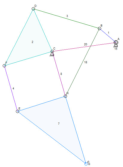
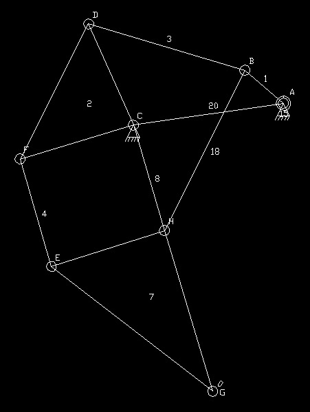
Here are my results so far. Text has been the hardest thing to handle.
Original Linkage Mechanism
DXF File Seen in Viewer Program
I find it odd that AutoCAD would default to a black background with white lines. This is a hold over from back in the 70’s when there were vector displays that had black backgrounds because that’s the natural color when nothing is being drawn. Now days, white seems to be typical because it matches what we see in the real world. The white on black is a bit annoying when you are not used to it.
I need to improve this by making the links into entities like polylines, polygons, or some other similar object type. I am not familiar with the DXF file entities enough to know exactly what I will use.
I also need to break things up into layers and also find out if I can fill in the links with color or if they should just be empty. I don’t think anyone uses color fill but I’m not sure of that either.
During the implementation of this feature, I moved all drawing operations into a c++ class that uses a contained object for actual drawing. The part of the code that makes a call like “DrawCircle(…)” doesn’t know if the destination is a bitmap or a DXF file. The lower level class doesn’t even know that because it created a contained class for doing the drawing and that object creation was the only time the specific destination was known to that code. It all worked out well as long as the idea that a DXF file is a drawing destination and not a saved file destination. Since things like auto dimensions are part of the drawing process and not part of the mechanism document, they are not able to be used in a DXF file if it were just a save file format.
The new architecture will be really handy if I try to use DirectX, OpenGL, GDI+, or any other drawing library, for screen, video, or other drawing output destinations.


