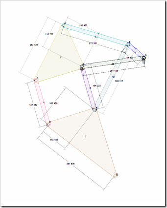
Jansen Mechanism with Measurements
I have added a simple “show all” dimensioning, or measurement, feature to the Linkage program. This was interesting because I wanted to automatically decide how to show measurements for links with three or more connectors.
For a link with three or more connectors, the process involves finding the longest distance between two adjacent connectors along the side of the link. The geometric hull of the link is used to find this information since it includes only those connectors that are on the outer edge of the link and also provides a list of connectors that is in order clockwise from the “first” connector.
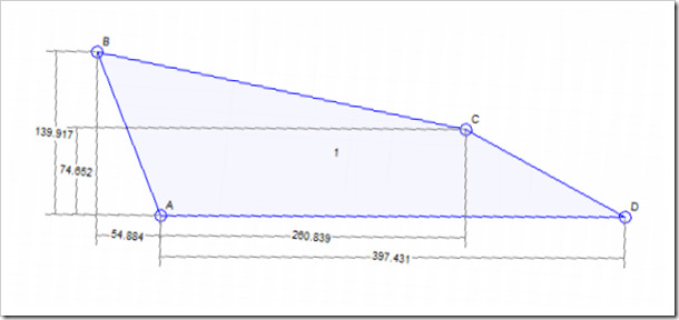
With the longest distance found, the line between the two adjacent connectors is used as a basis for orienting all other measurements. The reason I did this is so that a person could manufacture the part in a drill press or mill with little effort. All measurements are from the start point that was found when searching for the longest adjacent length. The image below shows the end result and connector A is the start point for this particular link. The start point could have just as easily been any other connector had the distances been different.
Layout of Measurements
Once the start point is known and the orientation line is found, the measurements are drawn based on each connectors position along the orientation line. In the above image, the distance between A and B along the orientation line (known because of hints in the line angles and measurements) is 54.884 units. This is not the distance between the two connectors but rather, the distance along that line defined by AD.
I am not sure how best to display the measurements. For instance, I could show the roughly horizontal distances relative to B instead of A but then that style of measurement display might not work for other shaped parts. I do think that whatever connector I used as the start point in one direction must also be used as the start point in the other direction. IN other words, one connector will be the 0,0 (zero) point in both direction.
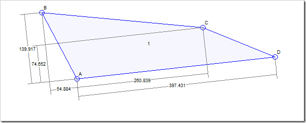
Part Rotated For Manufacturing
In the above image, I have rotated the picture to show what I was describing about manufacturing. This is the likely orientation of the raw materials mounted in a drill press or mill. The AD line is perfectly horizontal (in real life but not exactly so in my image) and the measurements are now used as x,y coordinates to drill the holes.
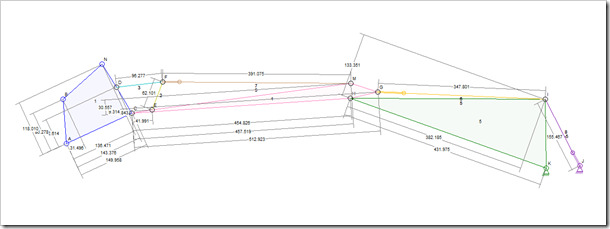
 Overly Complicated Measurements
None of this will be a good solution for very complex mechanisms. It will be too hard for a user to read the information in the image. I am still playing with the exact positioning but this is a good start.


