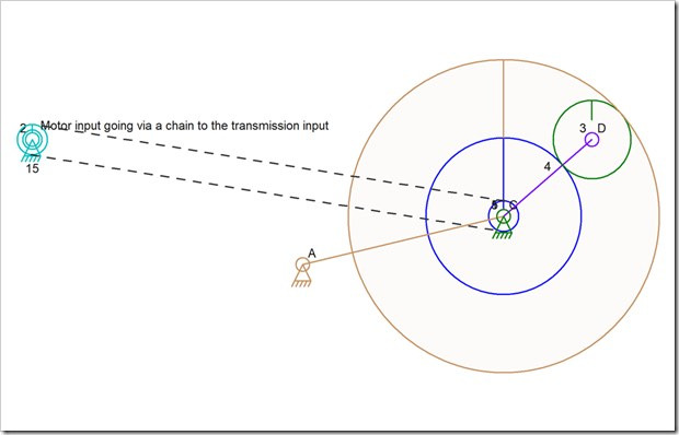
![]() I thought that the Linkage program, with the addition of external gears, would handle a planetary transmission just fine. I was wrong.
I thought that the Linkage program, with the addition of external gears, would handle a planetary transmission just fine. I was wrong.
Aside from the issue of having to drive this with a chain, which is necessary because making the center connector of the gear train an input causes all elements on it to turn with it, there is also the issue of gear 3 on connector D having two elements positioning it. This is like the problem I had with the Stephenson valve gear where a link with three connections to the outside world count not be positioned due to needing one of the connections to be fixed before the other two could be calculated.
if you look at gear 3, the center connector has nothing to hold it in a position; it is the mesh with the other two gears that determines where it will be located. in fact, the link 4 is not really necessary at all in a 2D world where the inner sun gear keeps gear 3 from moving inward and the outer internal gear (with internal teeth) keeps gear 3 from moving outward.
This is also similar to the sliding connector problems I encountered in the past where there was not one set of equations that worked for all gear features. This situation is going to need a special case function in the code!
The first thing I need to do is find a gear that meshes with two others that are in known fixed locations. Once the code has established the rotation of the sun and ring gears (gears 1 and 5 whose names overlap), the code can then succeed at detecting this situation. It will also require that both of those gears 1 and 5 have a common center point. When a gear is found that is between those two, or rather meshes with those two in some way, the code can also detect that one of those two mesh situations uses an external gear.
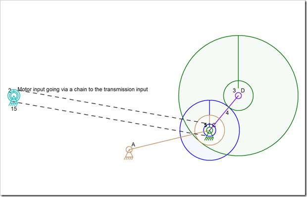
It is very possible to make what was the planet gear into the internal gear with a larger ration. the image above shows that situation. But it looks as if the code will handle it perfectly once it handles the other situation. The “planet” gear that now has internal teeth is still held in position by the other two gears.
I will need to mess around wit the math on scratch paper to find the center location of gear 3. it’s going to be weird because as the gear is rotated by the one rotating input, it is being rotated and moved along the inside of the ring gear and thus is rotating even more… or less… or something like that. Since I’m not a mathematician, I tend to experiment with ideas on paper to see how the parts relate to each other. This is where I wish I had some gears handy so I could just examine the ratios and see how the parts move; Where is that online gear simulator that does this stuff?


Thank you so much for continuously updating this amazing software! I have never come across anything that works as simply and effectively as this.
At the moment I am making a running horse which you can see on YouTube if you type in Running horse Automata and look for the one with my name on it.
One day I hope that your software could incorporate a way to draw shapes rather than just triangles and squares. To overcome this at the moment I create a shape with about an extra 30 add connector points to kind of outline the shape that I want to create. That way I can see which bits will hit against other pieces. If you can ever add a feature to create curved lines to a shape I will gladly donate $100 to your paypal!