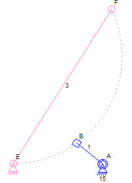
I have not gotten to the more complicated sliding connector situations and have only dealt with the simple cases so far. The simple cases like the one in the image below was not too difficult to implement.
Curved Slider Path
The mechanism in the picture above has a small radius for the slider path. The slider is on a rotating link and the number 3 link is moved during simulation to the proper location dictated by the sliding connector position.
There was a small complication in the user interface code. I needed to make it simple to specify if the curve is concave or convex. Since neither of those terms really means anything and it is just the side of the limit connectors that is picked when specifying the curve, I chose to use a negative radius to specify the “other” side. A check box in the user interface would have worked too although I would not have known what to call it. There is nothing in the mechanism that really defines a left or right, top or bottom, concave or convex, direction for the curve.
Here is a video of a working curved slider path:
Curved Slider Path Video
The next step in implementing these features is to handle the other sliding connector special cases.
Special Case Connections
I may have posted about it before but it is worth mentioning again. Each different way that links can be attached using sliding connectors require special-case code to handle the situation. This is much less of a requirement with rotating connectors where there are really only two cases that are needed and one of those cannot be simulated using simple math ( and is not handled in this simulator ).
For sliding connections, the special cases are all coded differently sometimes the sliding connector and its link are moved and sometimes the link with the slide path is moved. Sometimes a link is rotated and sometimes it is “slid” to the right position.
The video shows a link with a sliding connector being moved into position based on the link that defines the path. The opposite is true of the mechanism in the earlier image where the sliding connector link is already in position when the slide path link needs to be moved.
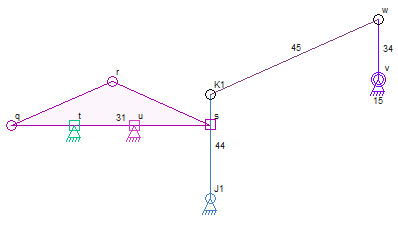
Add to that the special cases for links that slide back and forth on two sliders, with the sliders on that link or with the path on that link, and that’s four cases already. The complexity grows when a sliding connectors is used to define the position of the link that slides on two other sliding connectors:
Sliding Link Positioned by Sliding Connector
The mechanism above is just another of many special cases for simulating sliding connections. This one and others like it will be hard to handle with curved sliding connector paths for all sliders. They might be impossible for me to code at the moment due to the mature of the geometry needed to calculate all of the positions.
Dave


Hi there, Great Stuff,
You might be interested in MechDesigner from http://www.psmotion.com.
Actually, I think you have some really good ideas and your code seems flexible.
The MechDesigner software is really focussed at mechansims found in Packaging Machines.
Thanks for the Blog – Looks Good