
Since cam simulation involves finding the “best” place on a spline to place a sliding connector, there are bound to be small problems caused by the cam shape. I realized that this can actually cause terrible problems when a cam is using an open spline. The simulation difficulties can result in a sliding connector jumping to an unlikely-to-be-valid position. I’ll explain more…
For a sliding connector on the end of a link, the simulator calculates the position of that sliding connector by calculating a circle around the other end of the link using the link length as the radius. Then all of the points on the spline that intersect with that circle are found using some “simple” spline-circle intersection calculations. As far as I can tell, the number of intersections tops out at around 5 but the code has no limit and finds them all no matter how many or few. The next step in the process is to determine where the sliding connectors was expected to be by following a line through the previous two points and extrapolating a third expected point. This is never the right point but it a useful approximation to use when picking which of the intersection points is the one to pick for the new sliding connector position.
Imagine the following mechanism rotating clockwise in these two steps of the simulation:

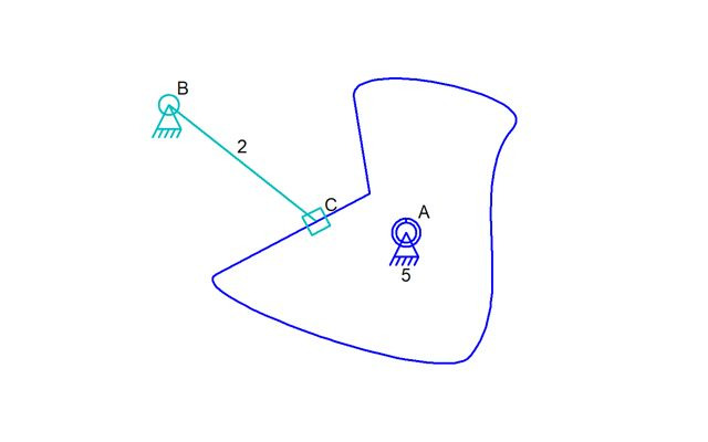
You can see that the sliding connector C jumped a long ways. The new position is one of two valid intersection points and one of them is much closers to the expected point than the other. The other would move C much further around onto the bottom curve of the cam. This is what a correctly running simulation should do if we are allowed to have the sliding connector “fall” to the new position. If that follower were a pin in a slot, this would still work in real life although the sliding connector would have followed the spline path rather quickly to this new position. Real life has what we perceive as an infinite number of steps between movements of time while our simulator only has 30ths of a second! Either way, this cam works as expected.
Now imagine the next cam shape also rotating clockwise with that sliding connector being a pin in a slot:
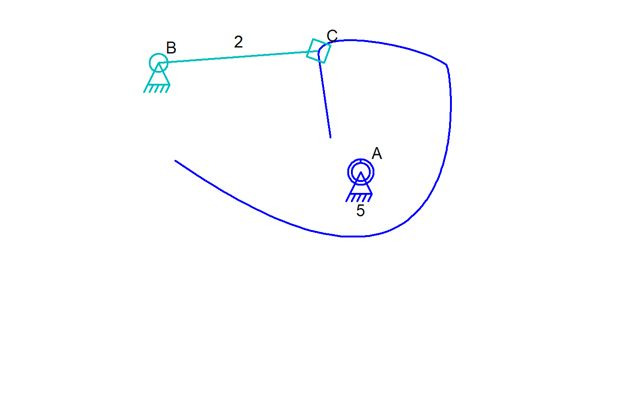
This is going to work even though it should not work. The sliding connector C will move down to the curve at the bottom. A few things come to mind when looking at this issue; The first thing is that detecting this particular situation would mean testing for the distance along the cam and detecting a large change. But what is large and what is ok? For a closed spline, the distance along the spline test would be more complicated.
This problem was very noticeable when I designed a vertical sliding garage door – the kind of door that follows a track vertically to a bend to horizontal. When one of the sliders moved off the bottom end of the track, it flipped up to be above the slider that was above it instead of below it off the end of the track. I am going to add code to detect an angle change of more than 180 degrees in order to detect that error. I might also try to examine the distance along the spline for each step of the simulation but then a reversing action might upset that test. It’s frankly a very difficult problem to solve!
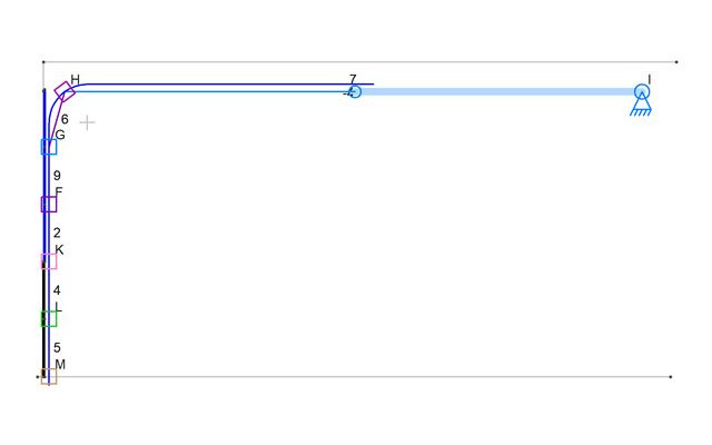
I added a picture of the vertical sliding garage door. It has some features that are particular to the tutorial I’m working on but the main issue should be obvious; If the door is moved down instead of up, the slider “M” at the bottom left will want to move off the spline but will actually be moved up above slider “L” since that is the only place the silumator can put it.
Oh yeah, I’m still working on that tutorial. I have the video recorded but now I need to do a voice-over since I didn’t talk while I made the mechanism. We’ll see how that goes!
Hey Dave,
I’ve been using the software to design some things for a DIY Project, and I’ve noticed that Linkage doesn’t like sliding mechanisms with gears.
It is specifically with the cases of gears restricting five-bar mechanisms on any of the three non-fixed points. Here’s a link to the images: https://imgur.com/a/y6X9coG
Hi, I sent a more detailed response to your email. But essentially, the actuator is being used incorrectly and the mechanism should otherwise work… except that I don’t know how to write code that will handle gears like that; Those gears will rotate once the actuator is fixed and that rotation will cause them to move the link they are on thus changing the angles of the links and rotating the gears more or less. In other words, there will be a feedback loop where the link angles turn the gears and that moves the gears changing the link angles. There will be equilibrium in real life but the simulator has no code for that – I just don’t know how to do it.