Although I do a bit of rock climbing now and then, this post is about cam lobes like those in car engines, not those used for rock climbing protection.
Finding End Circle Location
I was discussing this with my dad because he is building a model engine. He’s building it from scratch and it is a replica of a real engine. He needs to design cam lobes for the valves and was telling me about how he started with a bunch of information that he picked ahead of time and was able to compute the final bit needed to make the lobe.
The Starting Information
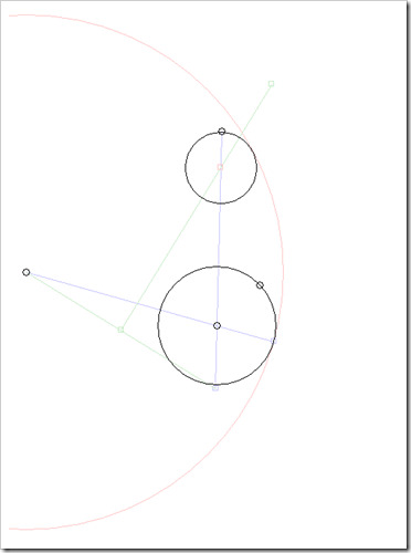
Base circle radius. This is the bigger circle that is around the cam shaft and when the cam follower is on this base circle, the valve will be closed and will not be moving. The rest of the information is all relative to the cam shaft and therefore, relative to this base circle. It is the bigger of the two black circles in the picture.
Angle for when the valve will open. This is the angle on the base circle where the love will go from being the base circle radius to getting bigger making the valve open. This is represented by the blue line in the drawing that is not the near vertical blue center line of the lobe.
Radius of the tangent circle. The sides of the cam lobe are not flat. If they were flat, the angle for when the valve opens could not be greater than 90 degrees unless the outer end of the cam lobe were bigger than the base part of the cam lobe. There is some art or cam design magic involved in picking the tangent circle radius. That circle is red in the picture.
Length of the cam lobe. This is related to the throw distance of the valve. Ignoring any scaling that happens because of rocker arms, the cam must be the same length as the distance that the valve will move.
With this information, the thing that is needed is a circle that is some distance from the end of the cam so that it is tangent to the end point of the cam and also tangent to the large tangent circle. The computed circle is the smaller black circle in the picture.
The tiny black circles in the picture are points that can be moved with the mouse. The angle of the tangent circle, or the angle at which the value will open, is not set as an angle since this is an experimental program. There are small circles to move the center of the cam shaft, the length of the cam, the radius of the base circle, and the center of the large tangent circle.
You can see in the picture that the small end circle of the cam is in the proper location and is the proper size to just what is needed.

