Running Crank Shaft with Connecting Blocks and Temporary Rods
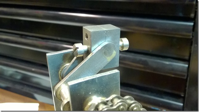
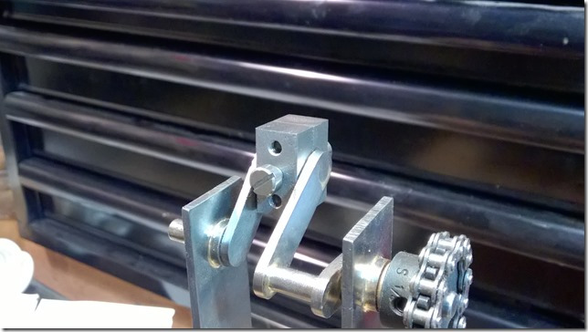
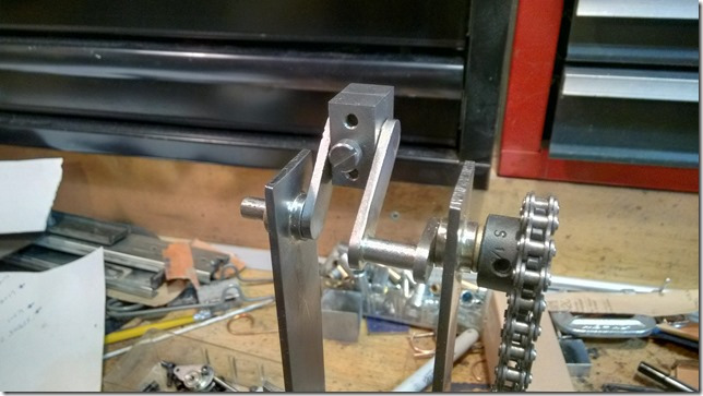
The video shows the two connecting rod end blocks in place. They each have a screw with a piece of 3/16 rod attached for the sole purpose of testing the blocks. The blocks will have rods attached to the screws on either side to allow the rods to rotate forwards and backwards relative to the crank shaft. This is because they will be attached to levers, not to something that only moves vertically.
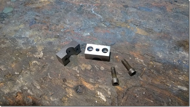
Crank Shaft Connecting Rod Block
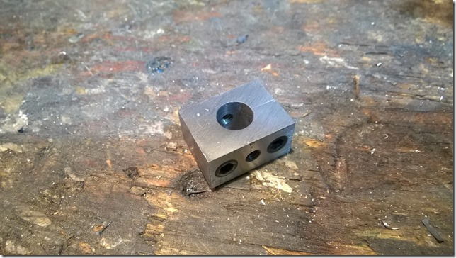
Crank Shaft Connecting Rod Block Assembled
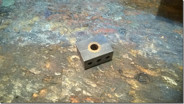
Crank Shaft Connecting Rod Block Assembled with Bearing
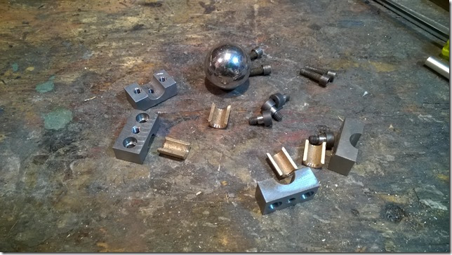
Crank Shaft Connecting Rod Block Parts (For 2)
I made the blocks out of a large block of mild steel. I cut it close to the right size using the now very slow band saw. Then I milled each piece to the right size. Then using the mill, I was able to get very accurate holes drilled; I hate switching to the drill press for the final drilling because it’s never exact and the back sides of the holes are sometimes off a visible amount. I guess that I’m just too lazy to get the drill press XY table perfectly aligned before switching to use the drill for the holes; I just drill them by eye.
After the holes were drilled, I tapped most of them and then went back to the mill for the counter-sink. I ordered the right size milling bit for this but I don’t have it yet. So I used a smaller bit and just turned the ends of the screws down on the lathe to fit in the counter-sink holes. The bearings are all cut and trimmed by hand – you can’t just split a bearing without a huge amount missing from the saw cut so a bunch of near half bearings got thrown out.
I need an engraver; I marked the inside of the blocks so that I could match them up properly later, but the scratches are not as visible as I’d like.

All I can say is WOW. Nice, nice , nice. Your good!