
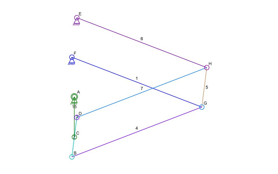
In the image above, there is a complexity that cannot be handled by the Linkage simulator. Although it might not look complicated, the lack of kinematic chain simulation in the software makes this impossible to simulate.
The Linkage software, as I have written about on numerous occasions, uses a fairly simple simulation algorithm. The Simulator looks for simplistic structures, mainly triangles, and then simulates them using circle-to-circle intersection calculations. For a few special cases, a specific equation is used, such as when calculating the position of a planet gear in a planetary gear configuration. For one special case where a link has three connections to the rest of the mechanism, an iterative approach is used to find the simulated location of one of the three connections (shown in the next image). Once a single connection of the three is found, the others are positioned using the circle-to-circle intersection math that is used for simpler pairs of links. None of the methods I used in the simulator handle the mechanism pictured above, as far as I know so far (spoiler: I think I figured it out later in this post).
The problem with this specific mechanism is the way the links resist movement invalid movements. In real life, the rotary input A moves connector C in a circle, and the parallel connections from connector C through the various links to the ground keep link 2 parallel to the “link” between connectors E and F. But mathematically, there is no way to calculate the position of connector B without already knowing the position of connector G. Connector G, on the other hand, cannot be positioned without knowing the position of connector B. There is a circular dependency in this mechanism similar to the circular dependency in the three-connection mechanism I already mentioned (and pictured below).
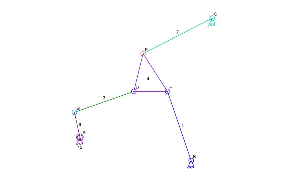
This three-connection mechanism is too complex to use the typical circle-to-circle intersection math used for most simulations. There is a circular dependency where E cannot be calculated until either D or F is calculated. All of the connectors in that triangle form a circular dependency. This was solved by my writing code that iterates through all possible positions of one of the connectors to then find the one valid location of another. I wrote this up in an earlier blog post so I won’t give the details here.
Back to this new problem, I am left wondering if I can use the same sort of iterative algorithm to simulate this. The first problem will be with detecting that this is a mechanism that uses this sort of parallel structure. I suspect that I can do a search of all links and look for two sets of parallels. But while I’m writing this, I’m imagining how non-parallel structures would still work in real life but with slightly different results. It would be better to find any four-bar substructure that hasn’t already been simulated and then just run the sub-simulation on that; The sub-simulation would iterate through all possible positions of the four-bar substructure and then for each iteration, find a set of valid positions for other connected links. I’m just not sure how to do that yet. Here is how it could work:
Links 1, 5, and 6, would be found to be a four-bar substructure that could be simulated through all of its valid positions. For each position, the rest of the mechanism would be simulated in the normal way (finding all links that can be simulated using circle-to-circle intersection math). Once that sub-simulation is run, if any of the links connected to the four-bar substructure are in a valid position, the sub-simulation is completed and another attempt is made to finish simulating any remaining links. This whole process is far more complex than when I do the sub-simulation on that link triangle because the triangle has a very specific configuration that I can detect. But perhaps these two situations are more similar than I initially thought:
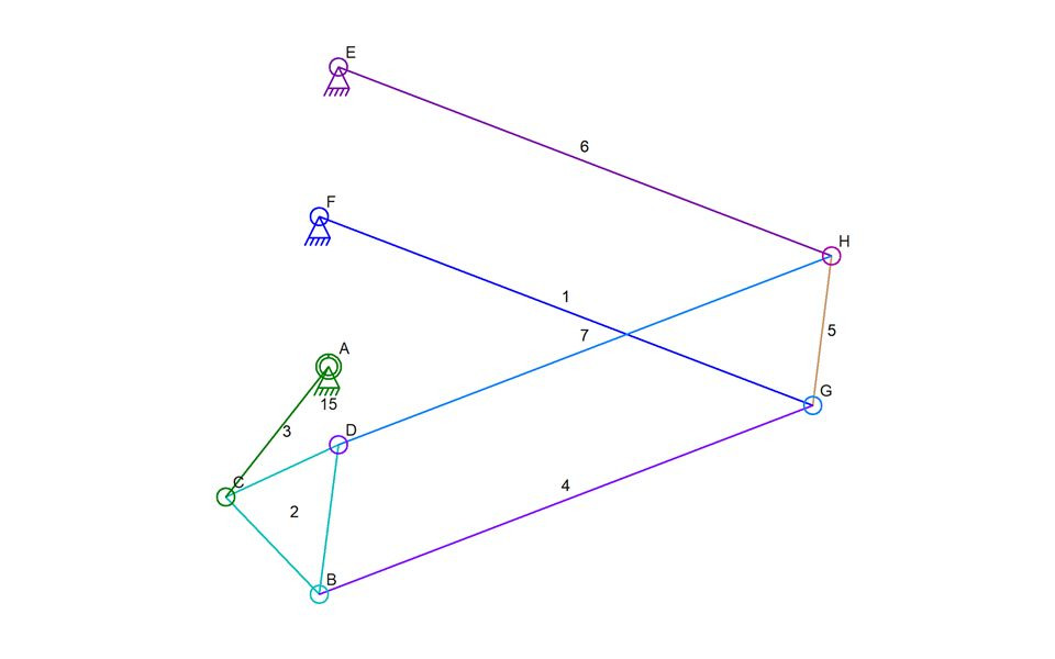
Examining the slight variation of the parallel mechanism (above), I see that there is a triangle link involved. If the software were to look for this triangle and detect how it connects to the rest of the mechanism, maybe it’s not all that hard to handle. Still, it seems like the real issue is the polygon formed by links 2, 4, 5, and 7. That polygon of links is, like the triangle in the triangle problem, connected to the outside by three connections. Note that it’s three connections since the simulator will have initially calculated the position of connector C based on the RPM and simulation step time. Also, note that none of the links need to be parallel for a mechanism of this structure to work properly – it would just behave differently when the links are not all parallel. A simulation of the mechanism below proves that point:
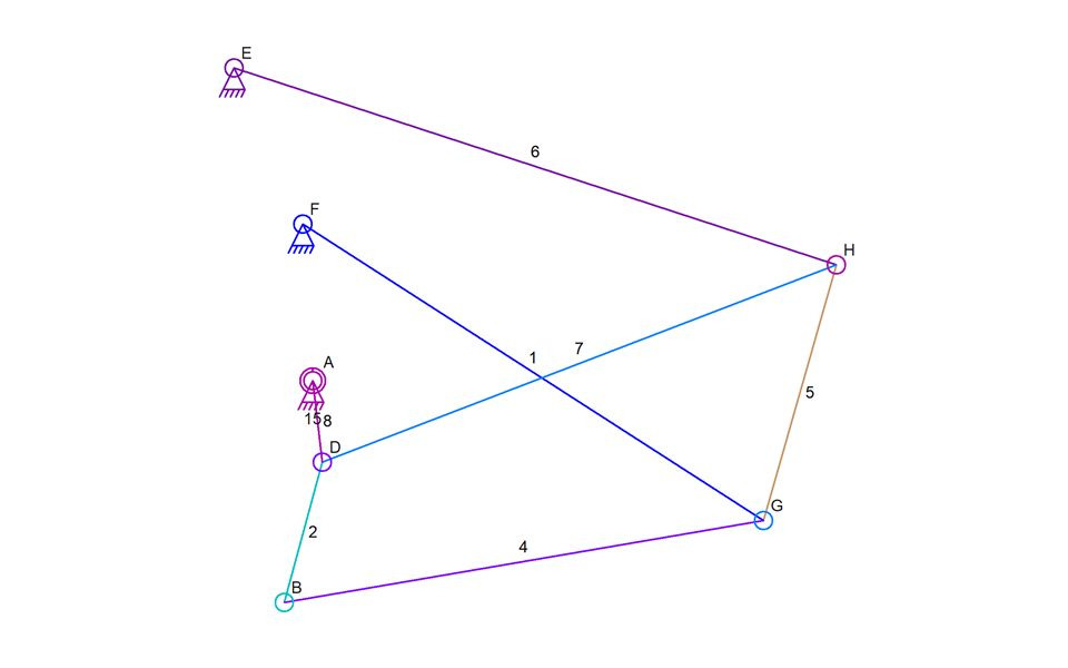
The mechanism above can be simulated because there is not a three-connection situation. I used a different connector of link 2 to be driven by the motor thus removing the extra step in how it’s connected to the rest of the mechanism. The simple circle-to-circle intersection math works fine in this case with connector H being calculated first, followed by connector G, and then connector B. All this mechanism above proves is that the relative angles and positions of the links and connectors are not the important factor in calculating the results – it is the polygon with three outside connections that is the problem with the original mechanism. And perhaps because this is, in fact, very similar to the problematic triangle mechanism, the same iterative approach can work.
Now the dilemma is deciding to work on this or to continue to port the existing Linkage software to the Mac!