
I am not a mechanical engineer but one thing I understand is ambiguity in linkages. It may be because I have a brain that is good at analyzing mechanical connections or because so many people send me mechanisms asking “why doesn’t this work?” Either way, it’s fairly easy to spot ambiguity once you understand where it comes from. And it always comes from the same thing.
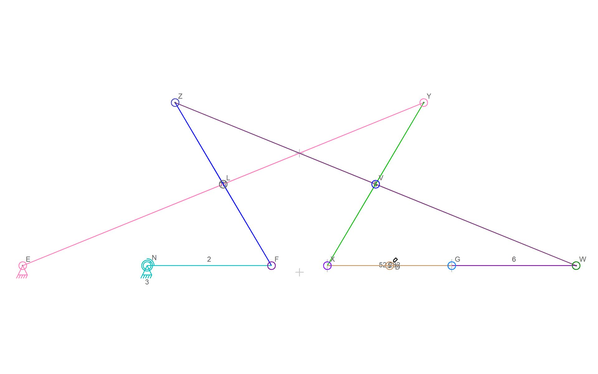
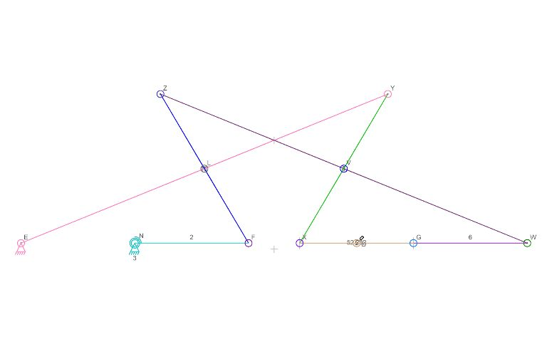
The ambiguity can be seen as the mechanism moves. Notice that connector D draws a line as it moves and that the line starts out straight. This mechanism is a straight-line mechanism and would be great except that as the mechanism starts and later passes this start point again, the movement of connector G is unpredictable relative to the connectors on either side. The two links 5 and 6, (with the 5 not being readable) are lined up perfectly and as connectors W and X get closer together, there is nothing mechanical to force G to move in one direction vs. the other direction.
I have seen numerous mechanisms with this sort of problem. If you look at a steam locomotive and only see one side of it, would notice this same issue present in the drive rod where there is a point of maximum extension that is lines up with the drive wheel center point. if not for the fact that the rods on the opposite side of the locomotive are offset 90 degrees, a steam locomotive could get stuck. I suspect that early steam engine designers know about this and either dealt with it like the locomotive wheels or relied on the operator to get the machine running in the correct direction were it to stop at the exact point of ambiguity.
I have not come up with a fix for this particular mechanism in the video. Because of that, I am reluctant to make this into a sample in the software or on the samples download page. I also don’t know how thang010146 health with this in his mechanism – he may have cheated somehow and his mechanism is an animation but not a true simulation.