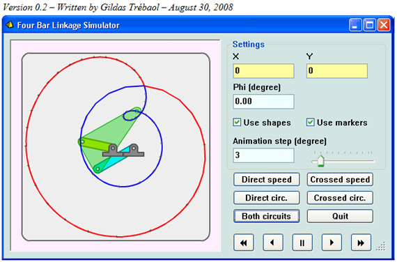
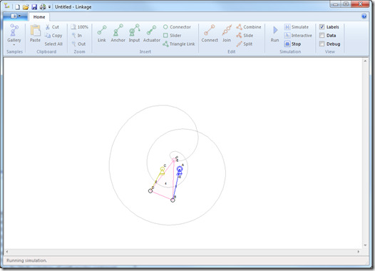
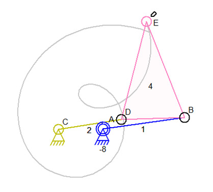
I found this animation of a simulator on the web. It came from http://gtrebaol.free.fr/doc/flash/four_bar/doc/. The interesting thing about it is the little twist that happens during the simulation.
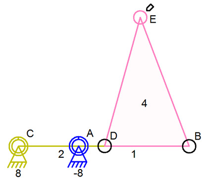
I quickly created a version of this mechanism using my Linkage editor/simulator program and found that I could not make that mechanism as easily as I thought. I was stumped for a moment until I looked more closely at the animation of the other program and saw that there is one position where A, B, C, D are all lined up. This mechanism only works because those connectors are exactly lined up.
It is interesting to me because a physical mechanism like this might not work as expected and certainly not like in the simulation.
A physical mechanism would have sag or droop because the tension of all of the parts would not be infinite and the mechanism would not be 100% stiff. In real life, connector D would be lower because it is stretched between C and B. Still, connector D might be dragged behind connector B as the movement is simulated and maybe it would work.
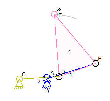
But even if that did work properly, there is a strange action in this mechanism when it behaves differently every other rotation of A. On the first loop of A, E moves left and D roughly follows B (dragged around by it). On the second loop of A, E and D both move upwards keeping D vertically even with B. The other simulator behaves in the same way. Here are images showing the movement, as seen by the partially drawn simulation line, at the two points where things differ for no obvious reason:
E moving left and D following B.
This is the mechanism just after it starts. C, B, C, D were all lined up.
E moving up. Note that D is not following B and is moving almost
parallel to it upwards.
This is intriguing. I think that the reason for this is that on the second loop, I is moving from a point below B and the simulator anticipates its next position as slightly above the original start position. This is a quirk in the simulation and I suspect that a simulation that had an infinite number of simulation steps would not show this movement.
The simulator always calculates an expected position of connectors based on previous movement in order to properly pick the actual position. This keeps the simulation from screwing up movement when positions might otherwise be ambiguous. There are almost always two different positions for a connector based on the position of some other connector and picking the right one of the two is very important for a step-based simulation.
The other guys simulator has the same issue.
As soon as I slowed things down to give more steps to a single loop, I get problems where the inexact alignment of the parts causes the simulation to fail. The mechanism must stretch one of the links to work for the very smallest amount of time when it starts and a faster simulation causes this configuration to get skipped. The other guys simulator probably doesn’t have this problem since his links were probably not drawn by hand.
I don’t know if the other simulator worked as that person expected and if he understands that the cool curvy result is a byproduct of the simulators weakness or if he thinks that a real-world mechanism would do this same thing.
When running a very slow simulation with a large number of steps, I get binding in the mechanism. My editor relies on mouse positioning so I was not able to get the links and connectors lined up well enough for a complete simulation. This might be another hint that the second loop of the simulation isn’t correct because D cannot move in the manner shown in the second loop without one of the links getting stretched, if just for a moment.

