I recently added a new feature to the Linkage program. The new feature allows an input to be manually controlled during an animated simulation. There are currently four types of simulations:
- Animated Simulation
The simulation is run in real time and the animation of the moving mechanism is visible in the editor window. - Interactive Simulation
Movement of all inputs is manual and no movement is visible unless the user changes the position of an input element. Any movements are visible in the editor window. - Manual Simulation
Simulation is manual and no movement is visible unless the user changes the “position” of the simulation. Movement is visible in the editor window. - Simulation
The simulation is done “instantly” without any control or animation. The only visible effect from this is that lines from drawing connectors will be shown.
During the instant simulation, manual elements do not move. During all other types of simulation, the movement of manual elements is always manual and there is a control for each manual element at the bottom of the window.
This animation shows a simplistic reversing mechanism like those found on a steam locomotive. The mouse is used to change the position of the one manual element in the mechanism.
Movie of reversing mechanism.
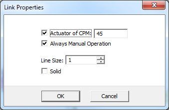
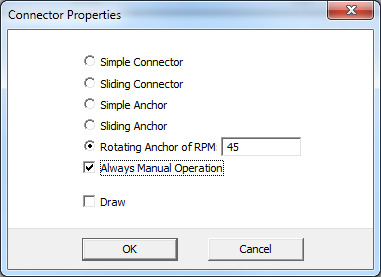
The manual control selection is done using the Connector Properties dialog box or the Link Properties dialog box.
Link Properties.
Connector Properties.
I have also changed the way the actuators are drawn when they are solid. The entire actuator had been solid and would appear to stretch when it moved. The two lines of the non-solid actuator were still visible. Now I make the moving line thicker and only enclose the “cylinder” part of the actuator in a solid border. A picture is worth a thousand words:
Solid.
Wireframe, line, plain, or whatever it is called to be not-solid.
My next feature will probably be the addition of cams. I have two ideas on how to handle these. One idea is to use the hull, or outer shape, of a link as a cam. I would need to display Bezier curves for the shape of a polygon link instead of the flat shape drawn now. That should be automatic but I am then not sure how to simulate the movement.
Six connector link with hull clearly visible.
Another idea for the cams is to have a cam shape that is separate from the shape defined by the connectors of a link. This would work the same as the previous idea except that adding points to the cam for controlling the shape would be a new unique feature. Dragging them around would be the same as for connectors or for the throw handle/knob on the actuators. A link could then have a cam and an outer hull that are separate and connectors could extend outside of the cam shape for connecting things. This is better but harder to implement because of the need for adding/deleting/moving the points that define the cam shape.
The cam follower would be a standard looking sliding connector and it would be connected to the cam in a similar manner to how it would connect to a pair of connectors. Moving it around would be tricky since it would be restricted to the cam lobe at all times.


