I have uploaded a new linkage install package. This incorporates all of the latest features.
I think that all of the versions of Linkage in the last year can only run on Windows Vista or Windows 7. This latest installer checks the Windows version to keep the program from being installed on Windows XP. I just don’t have the time or energy to figure out what is needed to make this work with XP and the reasons it won’t run are not at all obvious.
Some of the latest features are:
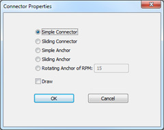
A more accurate Connector Properties dialog box. The previous version would allow a connector to be a rotating input even if it were not a ground connector. The problem was that it was not at all clear which links would rotate around which other links in this case. It certainly wasn’t programmed to work right so I now don’t allow that type of connector.
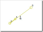
A better visual design for the actuators. The throw knob is round but smaller than regular connectors. Dragging it adjusts the distance that the actuator moves. There are also two different line types for the actuator. The thick light line segment is the throw portion of the actuator, like the cylinder of a hydraulic actuator, and the thin dark line is the moving part.
The Simulation pane of the ribbon was changed to include the interactive simulation option and the Run button is bigger to balance the look of the pane.
The interactive simulation mode was added. The control handles can be dragged to move the associated input or actuator in the mechanism. This makes testing of mechanisms like the backhoe sample much more realistic.
A popup gallery of insertable item is now available. Right clicking in an empty part of the document will show this as long as the mouse is not moved while holding the button. Dragging with the right button held down still pans the mechanism window. Right clicking on a connector or link now shows the connector or link properties.
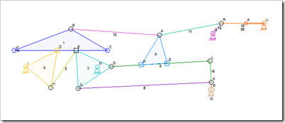
There were also some bug fixes in the code. Sliding connectors were not handled properly in some cases. A new sample mechanism is included that uses the situation that was not handled properly before the fix.
Upcoming Improvements
The next thing I will add is a measurement feature so that the distances between connectors is displayed. That will include the ability to select any two connectors and set the distance between them at a value that is used to scale all other measurements. I’m not sure how to show the control for this in the user interface but it will probably be a button in a new Ribbon Bar pane dedicated to measurements.
After the measurement display is working, I will add a link display feature that will show all of the links separately with a pair of connectors on each link rotated to be in the same vertical positions. Measurements between all connectors on a link will then be shown both directly and as x,y coordinates. The x,y coordinates could then be used to create the part using various manufacturing methods.
The exact x,y placement of anchors would then also be useful for making a mechanism to fit a read-world location and situation. Maybe some non-machine drawing features are needed as well.
Beyond that, I don’t yet know what would be useful to a mechanism designer.


