
The rolling bridge in Paddington London is a prime mechanism to reverse engineer and create with the Linkage software.
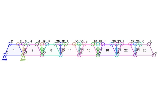
This is a simple repeating mechanism that uses the vertically-oriented hydraulics to decrease the distance between the top portions of the individual trapezoids. The distance decreases as the center of a pair of links is moved further and further from a starting point thus bringing together the other ends of those links.
This mechanism exposed a small weakness in the Linkage program and also presented some weird math problems that I didn’t expect.
The first thing I realized was that there would be eight of these trapezoids that would form the final octagon. I calculated 360 / 8 to get the angle I needed and then I realized that each trapezoid would have two sides that needed their angles to add up to 45 degrees. So the angle of each slanted edge should be 22.5 degrees. I started making the mechanism using this angle and soon discovered that with that angle, the fully extended hydraulic cylinder (and actuator in the software) would bring all of the edged involved in the movement into a single line. Real-world mechanical parts can’t do that and the Linkage software can’t accurate simulate parts that end up in this sort of ambiguous position. When retracting, the simulator would not know which direction to pivot any of the links so they could end up going the wrong way. Actually, real world parts would suffer from the same issue if they all ended up in a line – they would just need to be built layered somehow to let this happen. So I went past the 22.5 degree angle and the worked on the mechanism so that the top edges of the trapezoids would not come fully together.
Actuators in the software move at a constant rate and then instantly reverse direction at their ends. This has the effect of making the movement speed up as the distance between the “contracting” link connectors get closers together This effect of the speed changing when using linear motion and circular motion was very helpful in designing a mechanism a few years ago that needed half the mechanism to go slow and speed up while the other half went fast and slowed down. But here, it causes a small problem where the simulator can end up moving the trapezoids so fast that they take large steps during simulation and jump past their end positions. It’s a weakness in any simulation where there are discrete moments of time. Simulating more time steps helps this and the Linkage software simulates 60 steps per second while only displaying 30 of those steps. It’s still not enough to avoid the problem unless the actuator speed is slowed down a lot or if the distance movement doesn’t come too close to the point where the parts all line up in a line. I opted to use both ideas and use a very slow movement. You can see in the video that the whole mechanism moves faster and faster is it rotates. I also made the gap between the tops of the trapezoids further apart than I had first planned in order to be more realistic to what would get built in real-life. It works pretty well.
Once all of the trapezoids were the same shape and size, I adjusted the actuators to move just the right amount to get the mechanism close to perfectly closed at the end of the actuator movement. I decided to make a note to fix the software so I could set the throw distance for multiple actuators at the same time – doing it one at a time sucked.
I think that the same mechanism with some sort of rotary input would be better so that the movement stayed at the same speed as the machine rotates the trapezoids. I just don’t know a good way to do this and still have a buildable piece of equipment. Cables would work but once the bridge flips to have parts that are inverted, gravity would pull then in the direction they were moved by cables and the whole thing might fall down on itself. Lots of links might be able to handle some of the movement but with eight sections, there would be eight links all passing through the first trapezoid with some sort of pivot mechanism. The second section would have seven links passing through, and so on up to the last section of the bridge. Hydraulics makes the most sense because gears, however well they would work, would be numerous and a maintenance headache.
You can find a copy of the Linkage mechanism file here.
There is a small chance that some of my editing caused the trapezoid links to be uneven in their shape. I messed with this mechanism by hand a bunch before finishing it and one tap of an arrow key at the right time could have moved a connector a faction of a unit. I don’t suggest using this to build a real bridge without consulting an engineer ;)
Thank you for your quick intervention. Everything looks fine.
I just noticed the new version of Linkage. I’ll try to spend some time on it.
This is really great !
I would like very much to get the code but the link is not ok.
Thank you for everything.
Thanks for letting me know about the bad link. I fixed it and it should be working now.