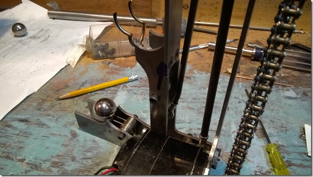
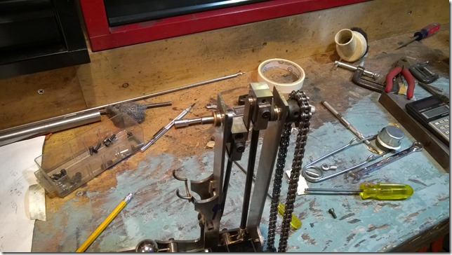
Running Crank Shaft with Connecting Rods and Both Bottom Lifts
I have a few still images for closer examination.
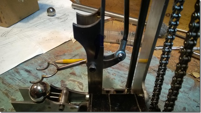
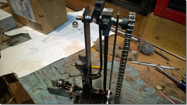
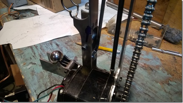
Note that he connecting rod to the middle lifter is bent; this bent allows the link to move to a position where a straight rod would bind, hitting the pivot tube of the lifter. I could have used a straight rod and changed the location where the rod connects to the lifter with a ball joint, but then there would be a bind at the top due to my not making enough rood for the ball joint to move further up. Those things happen when the mechanism movement is well designed but the physical size and shape of the parts is made up at build time.
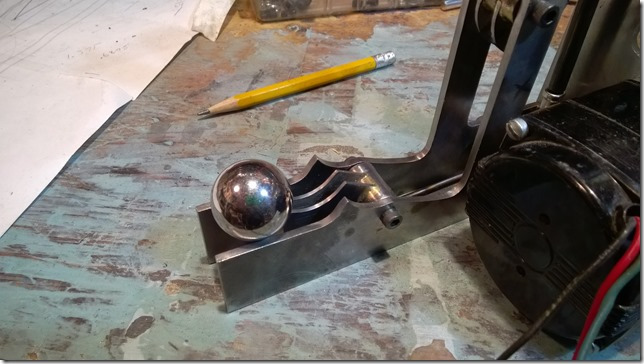
Ball at Bottom Lifter
Second Lifter at Midpoint
you can also see that the rod for the lower lifter is bigger than the rod for the middle lifter. That’s a temporary thing until I make a new rod. The rods need to be turned down on the ends to allow them to be threaded. Unfortunately, I already have a hole in the top fork of that rod that is too big for threading so a little step in rod size will happen there no matter what.
Second Lifter at Midpoint
Second Lifter at Top
Second Lifter at Top
The above image shows the bent rod and where it would bind. It’s actually really far away right now, but I don’t want to straighten it. having a slight bend might look like a mistake but a big bend is clearly on-purpose!
Second Lifter at Top
I was going to make a new crank shaft that is better aligned and has crank pins that are more even and smooth. But since this goes around at 3 RPM, it would take years to wear out the bearings. So this is how the crank shaft and most other parts will stay.

