Modified Freemantle Linkage or Evans Linkage
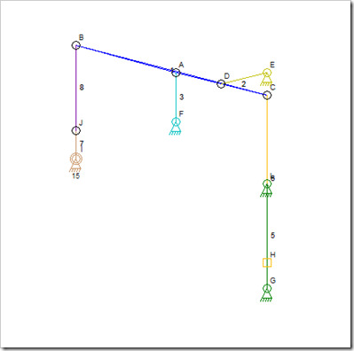
The linkage above cannot be simulated in the Linkage program (See Linkage 2.0). This appears to be a valid mechanism because there are three anchors all used to position link 1 (in dark blue). I am trying to decide how to handle this interesting case because having all three positioning links (2, 3, 8) parallel and of the same length would not be valid. I also need to start from scratch knowing link lengths and anchor locations but without knowing anything about the connectors to the main link 1 (in dark blue).
The problem is that I will start with three circles around E, F, and J, each with a radius as determined by the links 2, 3, and 8. With those circles and the distances and locations of A, B, and D, is it possible to determine the location of link 1? I need to be able to do this with a compass and straight edge before I can write the code to handle it.
If it matters, this is a steam engine apparatus designed to keep C and H running in line with link 5 (in green). And alternative to this is shown below:
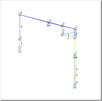
Watt’s "Parallel Motion."
The Watt mechanism uses a parallelogram near the end of the large link (link 1 in blue) while keeping the pivot of the large link in place. This can be simulated and works fine except for my inability to get the positions of the connectors and links exactly right to get the desired movement. I think that I am missing something in the early drawings of this.


