
The most important problem to solve with any process is letting people interact with it.
Software does processing; It is like a machine where you put something in at one end and something else comes out the other end. A drawing program let’s you put in mouse, pen, or maybe finger movements, and it does some work to change that into lines, colors, and shadings of a picture. machine and software convert things to other things. For a while (18 years), I wrote software that took in very little information from the user and it did a lot of work to create something from it. I worked in bioinformatics and I wrote software that compared large amounts of DNA or protein data to large amounts of other DNA or protein data. The information coming into the software was just sequences of characters and the software did work, with the help of some special hardware, to turn that into a ranking of best to worst matches. There was a lot of work happening in the software and very little input or output.
Now days, I work on mobile business apps. These apps do very little work with a lot of input and output. Keep in mind that there is more to the input than just data; The input can include taps and swipes on stuff displayed on the screen and that can result in very different things showing on the screen as a result. The key point here is that there is a lot of user input and not a lot of work going on inside the business software I write. That old bioinformatics software had hundreds of thousands of lines of code to figure things out but the business apps have tens of thousands of lines of code to do things like respond to a button tap and open a new page of data. A lot of the “source code” for the business software is definitions of pages, dialog boxes, custom controls, etc., and is not even computer programming code.
Where I am going with this is towards some issues in user interface design in the Linkage program. The Linkage program is sort of my “thing”; It is what I write about when I want to write about the ins and outs of software development. I could write about my day job where I have to write in Swift and Java and sometimes C# all on the same day, but that’s a bit boring most of the time. I would rather write about this topic of user interfaces and how they are such a problem for me. Let’s examine two features that I want to add to the Linkage software that are perhaps easy to simulate but are terribly hard to design for ease-of-use:
Serpentine Belts
The software supports chains between two sprockets. This is easy to work with because you the user would select two gears then open a dialog box and check a box (really, a radio button to be more specific) that tells the software to connect these two gears as if they are sprockets with a chain between them. The only different between a chain connecting those sprockets and two gears connected to each other is the direction one rotates when the other drives it. That’s it! It’s as simple as seeing there is a “chain” and then changing the angle of the movement from positive to negative or vice versa. Of course, there is also the code that draws the chain on the screen but it’s a minor issue. Sometimes what is draw on the screen is tricky because it’s hard to make things clear for the user, but a lot of the time, it’s easy to pick what to draw and write the code to do it.
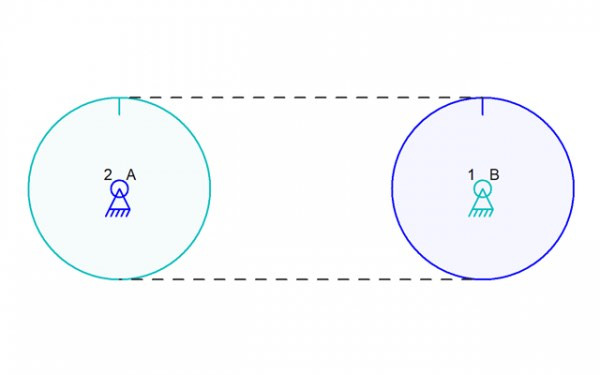
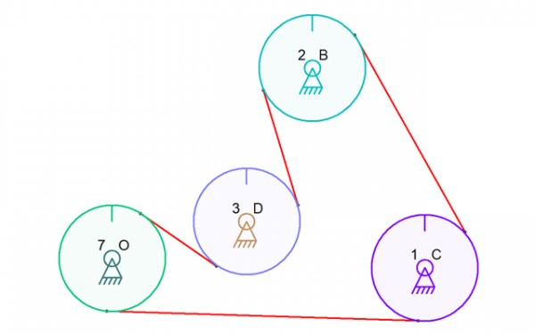
So on to the serpentine belt problem. The first thing to know is that what I describe could apply to just two “gears” but once the problem is solved for three or more, it’s easy to apply that two two “gears” with a belt crossing itself between them. And yes, I never know if I should stick with ‘sprocket” or “gear” or “pulley” so bear with me on that; All of those three things are kept track of as sort of a generic gear/sprocket/pully element internally to the software and it cares not if you are using chains, belts, or old leather ropes to connect your round thingies in real life. A serpentine belt would wrap around multiple pulleys so the “front” part of the belt travels along one pulley while the “back” of the belt travels along the next pulley. The software would need to keep track of this belt thing in some sort of data element and it would need to keep track of the pulleys. In the image below, I show a possible path of the belt using red lines and it’s fairly clear how the pulleys would move.
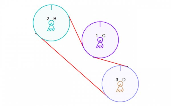
Two of the pulleys would turn the same direction as each other and the third in the middle would turn the opposite direction. If the software knew there were three pulleys, it could figure this out. The problem here is that the software doesn’t actually know yet how the belt passes around 1C (the middle pulley. Actually, it knows nothing about any of the pulleys but the obvious issue is 1C (the gear labeled 1 on the connector labeled C). There is an obvious alternative and the software cannot know what the user wants to do:
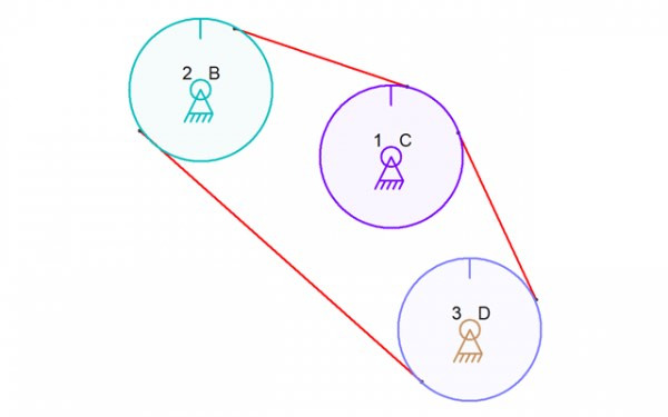
Now all of the pulleys would turn the same direction. There are of course other paths for the belts. There are two directions that the belt can pass around each of the pulleys.
So now we have the question at the crux of the matter: How do I build the user interface so the user can easily tell the software the path of the belt? This is what I was getting at in the title of this post, that writing the software to actually simulate this is easy compared to creating a user interface for it.
A List of Notifications
At work, I am working on adding a list of notifications, or messages, to the mobile app on each platform (“the app” from this point on). The notification can come as a push notification from a server and it can pop up even when the app is not running. The app will get a copy of all recent notifications from the server the net time it refreshes it’s data from that server, just in case the user ignored the push notification. And yes, if the user ignores the notification, the app has no way to ask the device or operating system to see all ignored, or even any, notifications that have shown up. It is up to the writer of the app to have a way to keep track of these things even though the operating system does keep track of these things to show you in some sort of “notification center”. My company sometimes develops features like this using a sort of AGILE/SCRUM workflow where we come up with some important requirements and then write the software to meet only those requirements. We see what isn’t right and then add pieces to the feature until the whole thing meets our requirements and meets the needs that were discovered along the way. This is often only a day or two of extra work. Right now, we are trying to deal with how to force users to acknowledge they saw a notifications and how to not force them to tap on every one of them just to mark it as “read.” It is actually difficult because I hate pestering users and making them do things they don’t need to do. My boss has a business need to ensure that a user can’t ignore a message too easily and that they must take some positive action for the software to know they read the notification message. It is a balancing act and we are probably better off with my always being as minimal as possible and my boss, sort of acting as a co-workers in this situation, wanting the user to do a heck of a lot more work so we are sure our customers, the businesses that have their employees use our apps, can hold their employee accountable. It’s the user interface that is the hard part of the software to design.
Back in the Linkage software, I’m at a loss for how to design a serpentine belt interface. The user needs to pick the pulleys, pick what order the belt passes around them in some cases, and which direction the belt passes around each. With three pulleys, the order doesn’t matter because it’s a triangle with each pulley having a belt connection to each of the other two. The belt can change which direction it passes around the pully but the order cannot change. With four pulleys, there are more possible paths with a belt having to go to two out of three other pulleys. Below are two pictures that show the four-pulley problem:
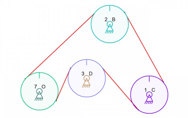
The order of pulleys is different in the second picture. And it is not simply reversed. Notice that using the link numbers, the first path goes from 1, 2, 7, 3. In the second, the path is 1, 2, 3, 7. Should the software simply require that the user decide when they select the pulleys what order to use? I could pop up a box when the user asks for a “ratio” for more than two gears and have that let them pick the order from a list of all possible combinations. The clockwise vs. counter-clockwise direction could also be picked for each gear in that case (and yes, I said “gear” because the round things are all gears until they are changed to be sprockets or pulleys by “meshing” them together. And the “ratio” is the size relationship between them and their actual size in the case of sprockets and pulleys. I just use gear terminology in the user interface in most places since switching terms is tricky and confusing sometimes).
With four gears sequentially numbered, the paths that are possible are 1-2-3-4, 1-3-2-4, and 1-2-4-3. There are no other paths because the belt cannot pass over any pulley more than once. The belt passing from pully 2 to pulleys 1 and 3 in one of thee possibilities – the other possibilities are passing from 2 to 1 and 4 or passing from 2 to 3 and 4. There is no other remaining option for the belt going around pully 2 and therefore no more than 3 possibly paths for the belt overall. If the user picked four gears in the software and clicked on the “ratio” button, they would get a list of these three possible configurations followed by a list of the four pulleys with a box to enter the size and a checkbox or other option for picking the direction. And now we are at the stumbling block that is always in my way of adding cool new features; The Linkage program is supposed to be simple and mouse-driven without a lot of typing. Setting a ratio for two gears requires a few option selections but this belt thing starts to get complicated. it’s a “complicated” that I really don’t like. I would like the user to be able to do this in some easier way. Of course I would certainly use the selected order of the gears to determine which configuration is selected when they click the “ratio” button. And if I’m clever, which I might or might not be in this case, I would be able to figure out how the belt can pass around the pulleys without crossing itself. It seems like a cool idea. But what hobbyist has ever used a serpentine belt? Check this out:
The belt that travels vertically in the Own and the Pussycat mechanical sculpture by Keith Newstead (1956-2020) around three pulleys. The belt looks like it might have trouble gripping the middle pulley but it was made to work and it certainly the type of thing a hobbyist might make. This is is the only example that I could find for this post but I’m sure that there are uses for a design tool that allows for this sort of thing.
Rack and Pinion
The rack and pinion gear configuration is another problematic feature. The first complication, which might be simple to handle, is the requirement that the rack not be able to change it’s distance from the pinion. This really means that the rack must slide on two connectors and those connectors must be on the same link as the pinion gear. Well, the alternative is that the pinion gear could be on the same link as two connectors that both slide between the same two sliding connectors. it is really only a difference between which link has the sliding connectors and which link has the two connectors that slide “through” them. So the easy part is done and the user just selects a gear and also selects a link that can move along a path that does not alter its position relative to the gear. But what about the ratio? If I am designing a rack and pinion gear train, I might want a certain ratio of movement; How big the gear is, is the only configurable item in this situation and it might be something that needs to get set and not change.
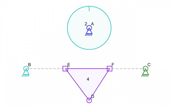
In the picture above, there is a gear 2 that could be meshed with link 4 to form a rack and pinion mechanism. Would the user select the gear and then connectors E and F to make it clear that those are the parts that mesh with the gear? I suspect that selecting just the gear and link would work since there is no way the software would not be able to pick E and F as the two connectors forming the rack. But does the gear get bigger so they mesh? That violates the rule (more of a guideline) that the Linkage software is made to let a user design the functionality of a mechanism without worrying about the form of it; if you want a specific gear ratio to get the movement you want, worry about the locations of the gears and their sizes later after you have the moment working properly. If you have a rack and pinion, you will probably want to have the rack move a specific distance when the pinion is turned a specific number of degrees. You can worry about the placement of the gear and the rack later after you see that the movement is just what you need. So now how would the user deal with this offset of pinion to rack and how would I deal with it?
I need to digress for a moment. I think that the software needs to let the user select a connector and a link and let them enter a distance from one to the other. It’s a feature that could at least help with the rack and pinion size and ration issue.
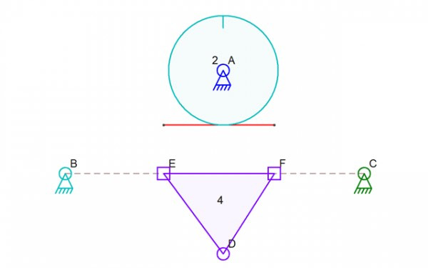
So back to the rack and pinion; One possible method of picking a ratio would let the user set a size for the pinion and then an extra rack line would get drawn showing the meshing of the two according to the pinion size and ignoring the distance to the line between those two connectors. I would want to be able to snap to that rack line but maybe visual alignment is good enough for an initial attempt at this feature. What might this look like? Maybe a dotted line? the red line below shows the location of this “rack” line. I can’t create dotted drawing lines with the Linkage software but maybe dots are the way to go – the same dots used for the slider paths. Or maybe actual dots of some sort. It’s hard to know what will look best.
This is the end of my post. These are the issues that plague me. There are times when I find that I can’t write the working parts of the software but more often than not, it is the user interface that requires most of the work. Don’t even get me started on the challenges of writing a Bezier curve editor.