Orbiting Gears and Chain Mechanism
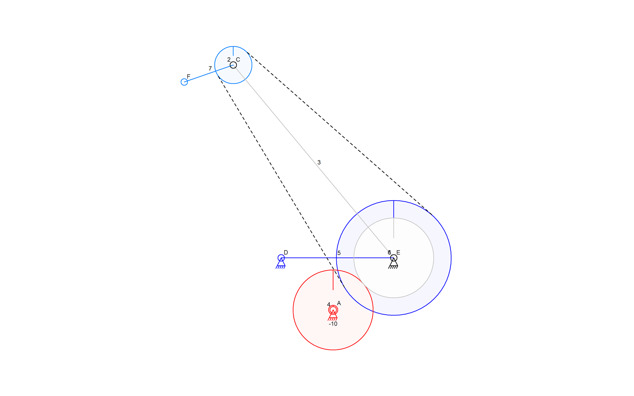
I’m having a little trouble with the Linkage user interface. In the picture above, which is a nicely exported and scaled down JPEG image, I designed a mechanism to show an orbiting planet (gear 2) with an orbiting moon (connector F). Designing this mechanism exposed some big shortcomings in the Linkage program that I don’t know how best to fix.
The two problems are related. First, I needed a sprocket that is anchored or fastened to the ground; It needs to never turn. There is no way to do this in the user interface except to create an actual link that has two anchors, and then fasten the gear to it.
The second problem is with the drive mechanism. Link 3 needs to rotate continuously, but cannot be driven by anchor E. Anchor E is just an anchor, not an input, because it would drive the main sprocket if it were an input. Instead of driving link 3 directly, I used a gear-to-gear connection.
This is all pretty clumsy.
Working Orbiting Gear and Chain Mechanism
One solution could solve both problems at the same time. I just need to add a check-box to the gear properties so that a gear can be anchored to ground, even when the connector is an input anchor. Then I would drive link 3 directly, and anchor the big “sun” gear. I hate adding settings like this because it stops people from creating mechanisms without looking at the properties of things. properties like this should be visible and settable directly in the editor window.
Ideas?
- Allow a gear to be fastened to a connector, not just to a link. Then I can at least fasten the sun gear to an anchor to visually simplify things.
- Don’t try to rotate gears and links that are anchored even if there is an input anchor driving them. This would bypass the need for a separate drive gear since the sun gear could be on the input anchor yet still not get rotated (since it would be fastened to another separate anchor).
These seem reasonable and all of the user control over this is in the main window, not in a properties box.

