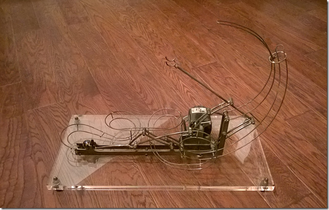
I need to name these things somehow. I’ve been using the colors to name them, but this one is a sort of muddled blackened steel.
This post contains a video of the finished sculpture as well as some historical photos and commentary on the construction of this RBS.
Black Rolling Ball Sculpture
Black Rolling Ball Sculpture
I don’t know what inspired me to build this lifting mechanism, but it was probably a combination of things. I had wanted to make something mechanical, and I wrote the Linkage program just for designing things like this. I’m sure that I saw some other mechanisms on other peoples sculptures, because there are a lot of great pieces out there, and I’m always looking for inspiration from what I can fid on the internet.
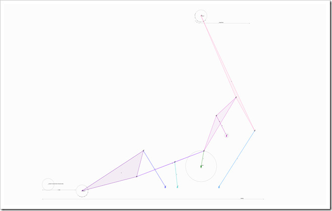
The plan started to come together when I started designing the mechanism with the Linkage program.
Mechanism Design in Linkage
Once I had a working design, as seen in the animation below, I was able to start construction.
Animated Mechanism Design in Linkage
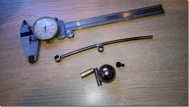
The First Part, with Ball and Calipers
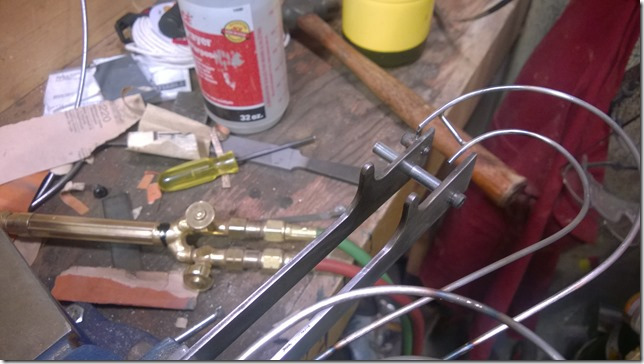
In the picture above, I took a 3/16 steel rod and gave it some curve. I then brazed on a piece of tubing on the end and in the middle. Next to the steel ball is a threaded steel spacer. That spacer will get cut to length and each piece will get stuck into these two tubes. The other links seem in later pictures, are forked and will go around these tubes with spacers. Those other links will then get screwed onto the spacers. Since the spacers will rotate in these tubes that I just described, they will form a hinge and let the links pivot at these tube locations. More than half of the connections in the mechanism are built this way.
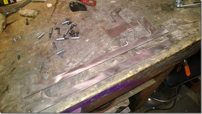
Frame Parts
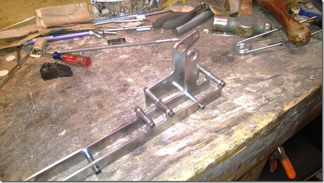
Assembled Frame Parts
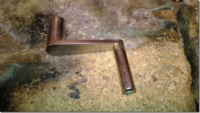
Motor Crank
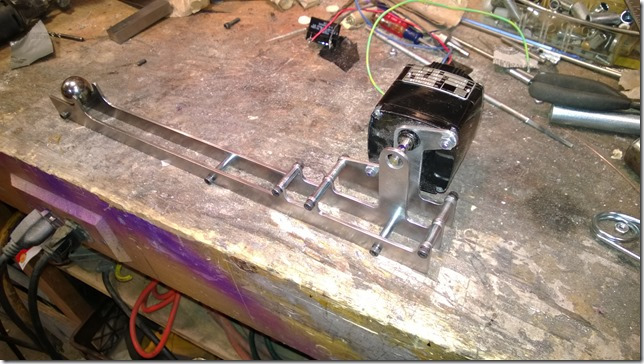
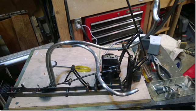
Frame Assembled and Motor Mounted
Early Parts Test
Another Early Parts Test
Bottom Lift Parts
Bottom Lift Finished
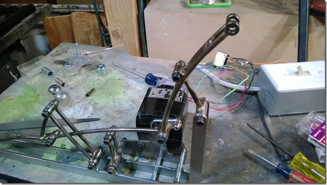
Starting Work on The Top Lift
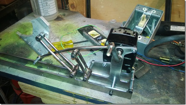
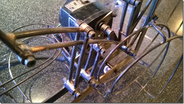
It may not be obvious, but the picture above shows some significant changes to the frame of the mechanism, from those shown in earlier pictures. The long frame rail near the motor had a vertical part that went up and over the motor crank shaft. It was cool looking, but didn’t leave enough room for the crank to have multiple links attached to it. You can also see two long vertical parts on the end of the rails were added to hold the small link for the upper arm. I was going to use one or two rods for that, and have them fixed in position, but there wasn’t room for them to be built that way, and these new pieces fit better with the overall style of the work.
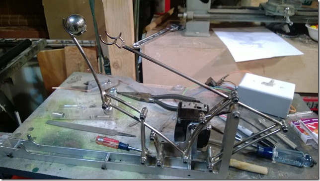
Everything Working
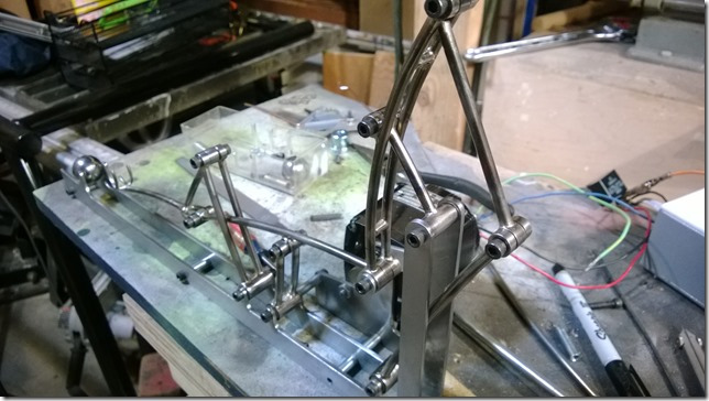
Another Angle – Polished Metal Looks Good
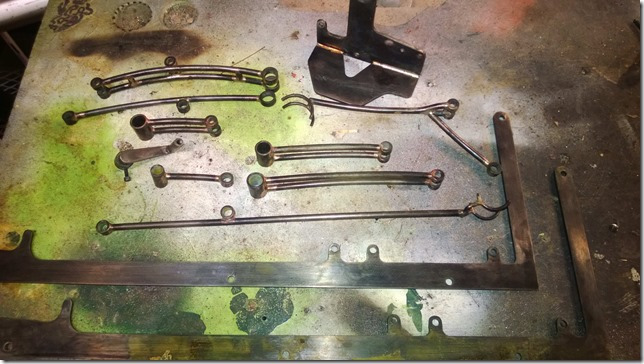
Parts being Blackened
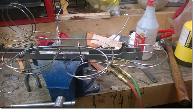
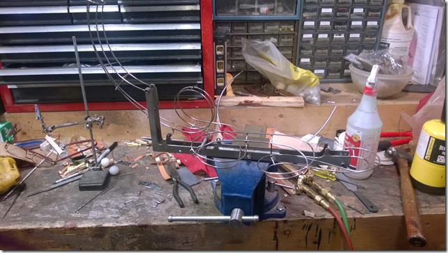
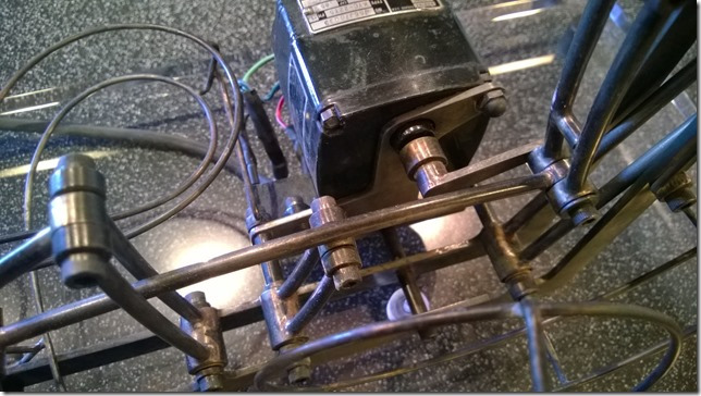
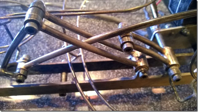
The picture above shows all of the parts being blackened. In this picture, you can see the forked links that I described earlier and the “knobs” on the ends that clamp down on those short threaded spacers. You can see more links with the small tubes on them. You can also see larger tubed on some of the links. The larger tubes will hold a bronze bushing about 3/4 inch long. Inside of that will be a steel spacer that is just a few thousandths of an inch longer. These will go between the frame rails and are screwed on through holes in the rails.
The one exception to the connections that I’ve described so far is the one on the upper-most part of the frame. That one has no bushing. I used a smaller outer tube for this one so that it would not look as bulky as the other connections that have bushing. I hope that a small amount of oil will keep me from regretting not using a bushing. but then again, steel-on-steel friction is minimal and this thing will not run long enough to every need new bushings, or to wear out.
Terrible Idea for the Track Structure – This Was Thrown Out
Attaching the Track
My dad suggested a short simple track. He was probably not thinking about why that was a good idea, but it was brilliant. I usually make complex and interesting tracks for my sculptures, relatively speaking, but this sculpture is all about the lift mechanism. A simple track get the ball to the bottom, while letting people see and appreciate the interesting lift.
More Track Construction
Notice that the frame rails and track don’t line up. The track is banked at this point, so the ball makes a very smooth transfer from the track to the rails. With a 1” marble, there is a slight bump because marbles are not actually 1” in size. 1” Steel bearings roll across this very smoothly and there is no bump at all.
What a Mess!
The Finished Product
More of the Finished Product
Another Angle of the Finished Product
I tried to get as many pictures as I could, but during some parts of the construction, like bending the rod for the track, I forgot to get in-between pictures. That’s a shame, because it was one of the more interesting tracks that I’ve build. The track screws onto the frame and no part, other than the frame, touches the base plate.
I also didn’t get any pictures of the base plate construction. It was simply a matter of buying a 3/4 inch piece of acrylic and then drilling some holes in it. Counter-sinking the holes for the frame mounts, which you can’t see in any of the pictures, was the most interesting part.
the feet are made from .75x.75 inch spacers from McMaster-Carr. I also got the threaded spacers used as the shafts that the bronze bushing are on, from McMaster, as well as most of the other size-critical tubing (in the form of unthreaded spacers). Screws came from them too, although I had those sitting around from a much older project.

Love it. I’m a big fan of both automata and rolling ball sculpture. Really impressive work! I love seeing the swings of the arms. I wish a lot that my mind worked in a way to dream these works up . . . Do you use a jig for your track or use the tie bars for spacing?
Ron