A user asked me about curved links in the Linkage program. I think that it is safe to say that curved slider paths is the desired feature because the visual representation of a link is fairly meaningless. It is the connectors that matter.
Straight Sliding Connector
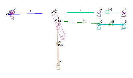
The straight sliding connector F in the image above slides up and down on the pink link. The mechanism is similar to a steam engine reversing mechanism but it is not technically correct. The straight path of the sliding connector should have a curve to it and that curve should have a radius that is identical to the length of link 4.
The Stephenson and other similar mechanisms, seen at Stephenson Valve Gear Wikipedia Page, all have a curved path for the sliding connector. This is essential for proper mechanism functionality because connector B in the mechanism above should not have any movement caused by sliding F up and down. Its movement should only be caused by the oscillation of the pink link.
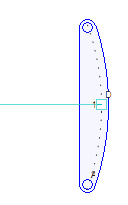
Curved Path
A curved path might be a property of the sliding connector that would affect the visual appearance of the link on which it slides. The code to draw this would be a bit more complex than just finding the hull from the set of link connectors and then drawing around it.
Another option is to finish the cam designer code and have a cam type that is an arc. Positioning the cam on the link will be tricky since the cam would not be the link itself. The problem with the cam idea ids that I am a long way from having a working design for the cam user interface. Interactively designing a cam is an easy feature to add but how the cam attaches to a link and how the user manipulates the sliders and the cam within the regular mechanism editor is still an unresolved issue.
I would also like to let the user specify the radius of the curved slider path using the mouse. This means having a drag handle between each pair of connectors in a link or between pairs of connectors that have a slider attached. The grab handle needs to be offset from the sliding connector and having two handles, one for the center of the arc and one for the outer edge would be the best option. The center handle would only appear once the radius was not infinity and the user could then drag it and snap it to the position of the connector that represents the end of a sliding link. In the first image at the top of this post, that would be connector B.
This is all just food for thought right now but making the path and the dotted line curved, and adding a test control to the sliding connector property box, are all easily done right now. Improved link drawing and mouse control over the radius are a bit harder to accomplish right away.
Dave


