? Linkage
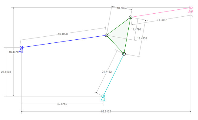
I don’t know if there is a name for this type of linkage. The green triangle link in the image above has a position (location and orientation) defined by the three ground connections and the lengths of the three connecting links. A search for equations to determine the triangle position has been unsuccessful at providing a mathematical solution. That solution, if it exists, is rumored to have six variables in six equations that need to be solved simultaneously (or something like that).
Presented here is a possible solution that involves minimal complex math by using an iterative approach. The down side of this idea is that it requires an unknown number of steps to find the solution and that it is possible to step past the solution if there are too few steps in the iteration.
The Problem
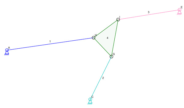
Diagram with Labels
Connectors A, C, and E, are at known locations. Lengths 1, 2, and 3, are all known. The angles and side lengths of triangle GHI are known. The goal is to find the coordinates of G, H, and I, given the other information. It is assumed that there may be no solution or multiple solutions to this problem.
There is a guaranteed solution to the problem as presented in the picture by simple fact that the picture shows the solution.
Iterative Solution
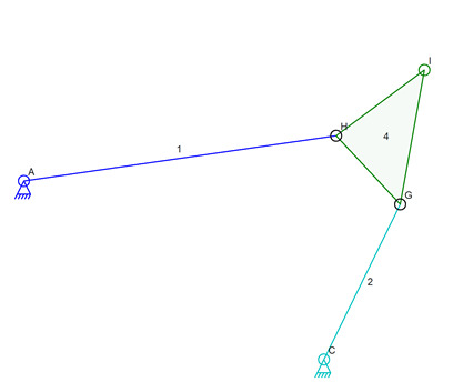
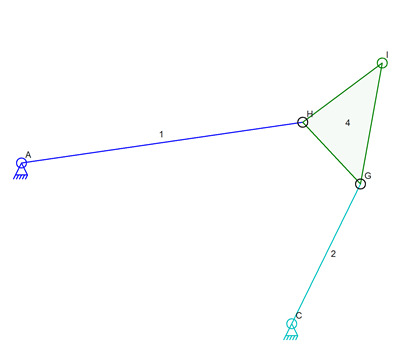
The first step in the iterative solution is to pick out a four bar linkage from this set of data. AHGC will be that four bar linkage.
Four Bar Linkage
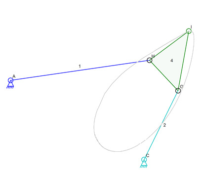
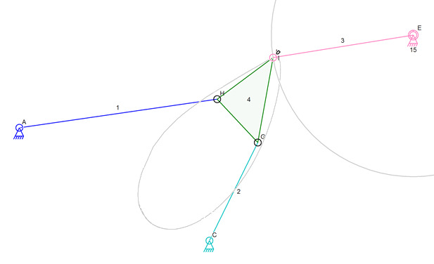
The next step is to simulate the movement of this linkage. The curved path of I is the desired result of the simulation.
Path of Connector I
Once this path has been computed, the four-bar linkage is no longer used. Of course having the actual computer program compute this path in one step before proceeding to the next step does not make sense. It is more efficient to do the next steps at the same time the path is being computed so that the data for the path need not be stored for later use. But for the purpose of this post, each step will be described before the next.
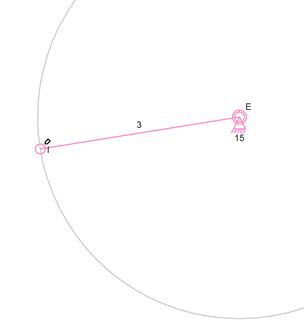
The next step is to compute the path of I around connector E. This is a circle and there is no need to do any iteration. The center point E and the radius defined by link 3 are used in the next step.
The Important Part of the Circle Around E
The final step is to find the intersections of the path of I and the circle around E. Each of these defines the possible locations for connector I. Where they intersect are the only places where connector I can physically exist.
Intersections and Possible Locations for Connector I
As the above image illustrates, there are two possible positions for I. The simulator code would pick one based on other factors such as the starting position of the various links and connectors as well as on the predicted new location of a connector that has moved during a simulation. If this were a static exercise and not being used for a simulation of a moving mechanism that has a starting state then there is no way to predict which of the two locations is correct.
One final step not shown in a picture is to actually find the location of H and G. H is very easy to compute because it is at the intersection of a circle around I of radius HI and of a circle around A of radius AH. The location of G is determined from the now known H and I or from H and C.
Skipping the Iteration
It may be possible to create an equation for the curved path of I as part of the four bar linkage and then use that and the equation for the circle around E to calculate the intersection points. This would avoid the iterative steps needed to accomplish this as described above. The math is simply too complex to figure out at this time if it is even possible. The iterative approach might actually be faster than the computations needed to do this with a single final equation.
Finally
I need to point out that the four bar mechanism shown below has simulation issues that need to be resolved in the existing Linkage simulation code. The Linkage program was not able to simulate this to get the entire curve for connector I due to the mechanism binding. The binding stopped the simulator even though a few more simulator steps could get the mechanism back to a non-binding state. Since it is a simulation to test mechanisms, stopping when binding is important. When finding the path of I, the binding is not important other than to skip past parts of the path of I that cannot existing physically.
Four Bar Linkage
There is also another whole path for I if link 1 and link 2 are allowed to be rotated all of the way around the mechanism to the then place the triangle at the lower left side of the various images. This will be a problem for the code that has no actual starting point to work with. The code will need to rotate link 1 around connector A and skip invalid positions. It will then need to rotate 2 around C and also skip invalid positions of the four bar mechanism. This should yield to possible paths for I with gaps in the path where the four bar mechanism would bind.
As mentioned earlier, the code would never take each step as described above. A small segment of the path of I would be computed as a line segment and that line segment would be compared to the circle around E. When a line segment intersects that circle, a set of shorter segments would be computed in that area and each intersected with the circle to get a more accurate intersection point. This would be repeated until a required level of accuracy was reached and then the code would proceed to the next rough grained line segment until another intersection is found or the path is complete. It is also possible to quickly test a segment for its distance from the circle to skip past it without doing the more complex intersection computation.
One flaw in the iterative approach is that the granularity of the steps needs to be fine enough to not find an intersection when pone physically exists.
This is the idea for simulating the three link triangle problem.
Dave

