
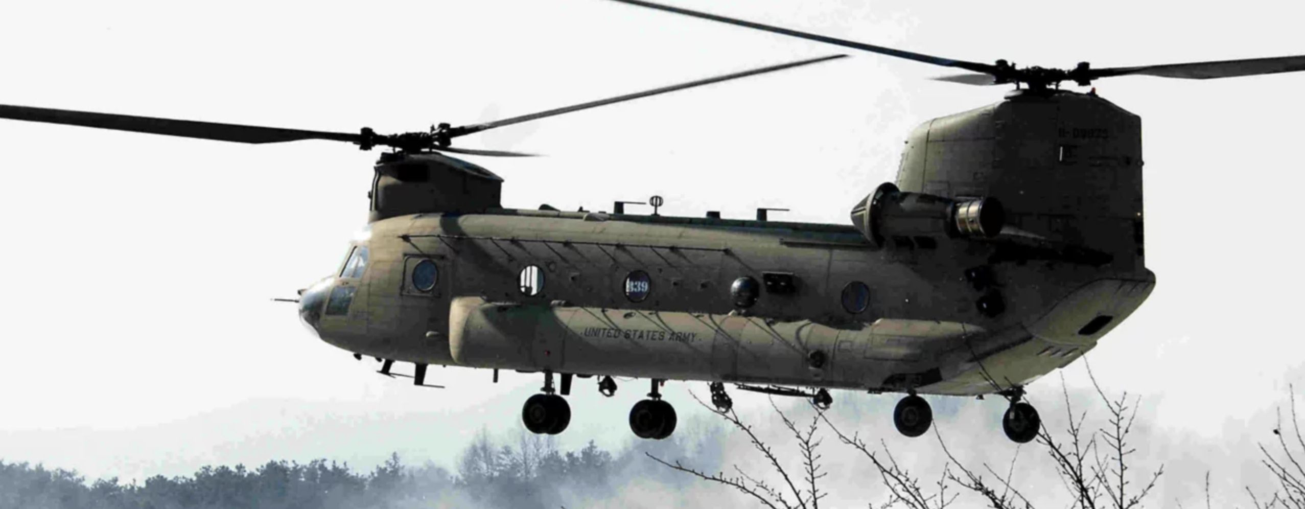
I had a fairly terrible idea to convert two $80.00 RC helicopters into a single CH-47 Chinook. The Chinook has two rotors, one forward and one aft (very different from the V-22 Osprey that has rotors on the tips of the wings). It’s a terrible idea because of the complexity of it and the likelihood of failure. Still, it seems like it might be fun to try.
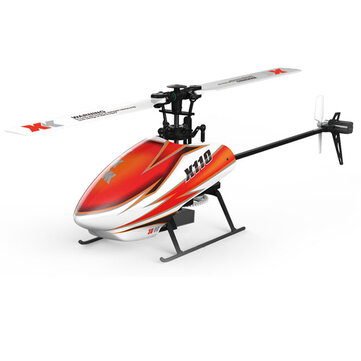
I have been flying the XK-110 helicopter sold by Banggood (yes, that’s the name of this Chinese company selling tons of things like this). This was the highest rated RC helicopter of this size on a few sites so I picked it. The idea is to take the guts of two of these and make the Chinook from them.
Before I describe what I think is needed to make this project work, I need to describe how a helicopter works. Almost everyone knows that a helicopter has rotors that spin and lift the vehicle into the air. And most of those people will realize that if the rotors are rotating in one direction, the helicopter will want to rotate in the other direction – that’s why there is a tail rotor, to contradict that movement. I have no idea how many people know about cyclic pitch control and gyroscopic precession. So he is a basic education on helicopter aerodynamics:
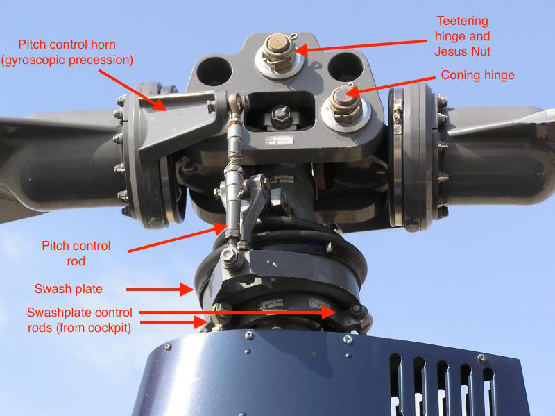
A simple helicopter will have a motor that drives a vertical shaft. At the top of the shaft is a set of mechanical linkages. The rotor blades are connected to that main shaft using a sort of hinge so that the pitch of the blades can change. It’s not an up and down hinge but rather, it’s a twisting connection that allows the blade to rotate to increase the pitch (raise the front edge higher and the back edge lower) or decrease the pitch (front edge lower and back edge higher). Think of how an airplane pilot might pull back on their stick to pitch up the nose of an airplane thus causing there to be more lift to make the plane go up. The blades of the helicopter can pitch up and down to increase and decrease the amount of lift. To make this happen, the rotor blades of a helicopter have a small lever arm that stick out from the blade that has a connection to a spinning disk that surrounds the main shaft a bit below the blades. This spinning disk is attached to a non-spinning disk using bearings like a lazy Susan on a dinner table. At the dinner table, the lazy Susan can be spun around but it remains “attached” to the dinner table. If you lift the dinner table, the lazy Susan would lift up also. That’s what the helicopter has – a lazy Susan that can lift up and down. The rotors are attached to the top of that lazy Susan, which is really called the swashplate, and when it moves up, that pushes those small levers up and that pivots the blade and increases the pitch. That’s how a helicopter lifts off the ground, by lifting the swashplate through linkages to the controls in the cockpit. Oh, and the pilot must also control the speed of the rotors because increasing the pitch will add drag and the pilot will need to increase the throttle. And yet there is more! If the rotors are listing more then the counter-rotating force on the helicopter will increase and the pilot will also need to change the pitch to the tail rotor to counteract this counter-rotating force.
Fortunately for me, the XK-110 radio-controlled helicopter has gyroscopes in it, or other similar devices, that detect that counter-rotation and automatically compensates for it. The small helicopter just changes the speed of the tail rotor automatically as needed to keep pointed in the right direction.
The last this to control in the helicopter, since I covered the up-and-down and the rotation (using the tail rotor, which should have been obvious since I mentioned it’s used to stop the helicopter from rotating), is the movement front, back, left, and right. The swashplate is connected to the controls in an ingenious way so that it can be tilted in any direction. Remember that if the entire swashplate is moved up and down then the overall pitch of the rotors changes overall. if the swashplate is tilted then the rotor pitch will change as the blade go around. By applying a left movement to the stick in the cockpit, the swashplate is tilted to the left and the right side of the rotors is lifted and the left side is lowered. This causes some of the blade force to lift the helicopter and some of it to push the helicopter to the left.
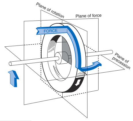
Now for a quick lesson on gyroscopic precession. If you have ever held a spinning disk in your hands, you will have noticed that it is hard to make it change direction. You might have also noticed that if you try to change its direction, it wanted to change its own direction differently from the force you applied to it. This is called gyroscopic precession and there are great YouTube videos explaining it. The rule is that if you apply a force to the gyroscope, which is exactly what the spinning blades of a helicopter are, the actual change happens 90 degrees after that force is applied. it’s because when you apply a force, you are applying it to the actual material of the gyroscope that is spinning and that gyroscope material wants to continue in that new direction. Apply an upward force 20 degrees from the “front” of a spinning gyro and the gyroscope material starts its upward movement at that point and it keeps going up until it’s gotten 90 degrees further along its rotation (at the 110 degrees from “front” point). At that point, that material of the gyroscope starts moving back downward for a full 180 degrees of rotation and then starts back up again. if it doesn’t make sense, just accept it and watch a few videos until it makes sense.
Back to the helicopter. The connection from the swashplate to the rotor blades happens to be 90 degrees from the center of the rotor pivot. If you tilt the swashplate forward, that’s actually increasing the pitch of the blades on the left side of the helicopter and decreasing it on the right side. And due to gyroscopic precession, it’s tilting the blades so they are higher in the back and lower in the front. With this little RC helicopter, that force simply lifts the back of the helicopter and lowers the front. And away it goes, forwards.
In summary, the controls on the RC helicopter consist of the collective pitch – the up and down movement of the swashplate to increase and decrease overall lift, the cyclic pitch – the titling of the swashplate to tilt the rotors and give the helicopter a directional movement (which can even be backward and sideways), and the tail rotor to control yaw – pointing the nose of the helicopter in different directions. The transmitter that controls the RC helicopter has two sicks with the right stick being the cyclic pitch control and the left stick being the collective pitch using up and down movement and tail rotor control using left and right movement.
The Chinook is a bit different. I’ve been reading some of the official user guides to the helicopter – yes there are user guides for big two-rotor helicopters – and it’s quite a bit different from the small RC helicopter and from many smaller full-size helicopters. The obvious difference is that the Chinook has two main rotors and no tail rotor. Let get deeper into how it works…
The Chinook rotors are connected with at least one more hinge. The blades can actually move up and down as well as pivot to change pitch. Since they spin so fast, that outward “pull” flattens them out quite a bit. This hinge makes it so that if the cyclic pitch control is applied to tilt the rotors forward (lower in front and higher in the back), the blades can actually follow that tilted path without tilting the main rotor shaft. This is essential for rotating the helicopter without a tail rotor. To change direction (yaw to the left or right), the cyclic pitch on the front rotor is moved in one direction, tilting the swashplate and tilting the rotors, and the cyclic on the back rotor is moved in the opposite direction. Since the entire “disk” of the rotor system in the front can tilt, as well as the back, there can be a sideways force applied to the ends of the helicopter and it yaws left or right. It would still be the “rudder” pedals in the real helicopter that control this, just like in a smaller single rotor helicopter. Interestingly, the user guide also describes using this tilting rotor mechanism as a way to have forward and backward movement so that the entire helicopter doesn’t need to be tilted forward to move forward. This results in the helicopter being more aerodynamic since it has a very long body that would otherwise create a lot of drag. The user guide also says that some amount of collective pitch control is added to the rotors so, during forward travel, the front rotor has a little less collective pitch and the back rotor has more collective pitch. It’s not really during forward travel that this is the case, it’s really just at the start of forward travel when the pilot applies forward stick to move forward that the nose drops a bit and the rotor disks (“disk” being the entire area that the rotor blades spin through) tilt forward.
I’m not 100% sure about how much the rotor disk can tilt using those extra hinges at the root of the blades. In fact, I’m only 99.999% sure that the main rotor shafts are totally fixed in position. But it makes some amount of sense mechanically and aerodynamically.
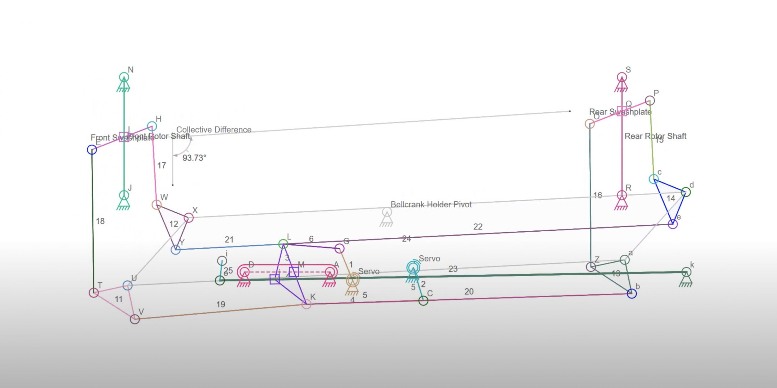
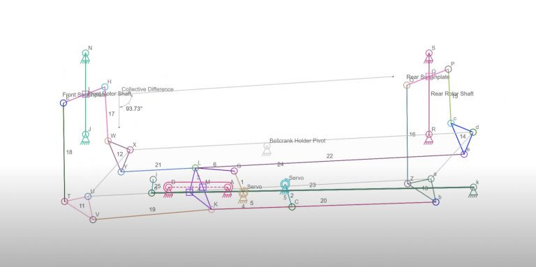
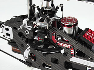
So how do I create a tiny functional Chinook from two of the XK0110 helicopters? The first thing is to understand how the controls are attached to the swashplate. In the XK-110, there are three servo motors that attach to the swashplate in a triangle configuration. There is one connection in the front and two in the rear. The triangle is equilateral and each servo is attached 120 degrees from the others. If collective pitch is needed, all three servos move their arms up and down and the swashplate moves up and down. If cyclic pitch is needed, the servers move to tilt the swashplate in the direction of the control stick by moving one or two of the server arms up and the other down. The transmitter actually does the math to convert the stick movement to the correct servo movements. Finally, the speed of the tail rotor is changed to maintain the heading of the helicopter and to make it yaw. Speed up the tail rotor to yaw in one direction and slow it down to yaw in the other direction. That control is done on the helicopter where the input from the stick is combined with some gyro input in the receiver to figure out the correct tail rotor speed. Also, the main rotor speed is controlled by the transmitter and is mixed with the collective pitch control so that the motor gets more power when there is more collective pitch applied – this keeps the rotors spinning at roughly the same speed regardless of how much collective pitch is used. There are other modes like “full throttle” where the motor runs at 100% power no matter what, something that could never be done in a real helicopter.
To make the Chinook, the hardest part is figuring out how to get the yaw controls to work. The radio receiver does have a tail rotor output that goes into a motor speed control so that could be converted to run a servo. And that servo could move a linkage that tilts the two swashplate left and right, or right and left, to get yaw control. But would the little blades on the RC helicopter flex enough if the whole helicopter can’t tilt so that they actually lean a bit left and right and therefore rotate the helicopter? The reason I’m worried about this the most is that there is no way to add a small hinge to let the rotor disk tilt easily. This would be the first thing to do – mount the helicopter to a bench, power it up, and then give some collective pitch to see what happens to the blades if the main shaft can’t tilt.
So let’s assume that the blades can flex enough to give reasonable yaw control. The next issue is how to get forward and backward movement. If I want to get good forward speed, I suspect that I would want to alter the collective pitch to lower it in the front and raise it in the back. Sure, I could probably combine collective and cyclic control like in the real Chinook, as long as there is a way to connect all of the linkages to do this. That leads to actual mechanical stuff and connecting the three servos, plus the extra for the tail rotor, to a bunch of links so that all of the various inputs get combined. I know how to make linkages and it’s not even that hard to add link movement together with enough extra little parts. but I have no idea how to do that since I would want to keep the three-servo collective/cyclic servos and then feed those, along with the yaw control server (tail rotor) into those same linkages. It’s all a rather interesting problem.
Oh yeah, and the front and rear rotors spin opposite directions so that the yaw control can be minimal when no heading change is needed. The Chinook is also designed so the rotors overlap but never hit each other because they are both, front and rear, run off the same engines and transmission.
This is the idea for now and hopefully writing it down and making some sketches can get me a little further along with this project. I’ll need to spend another $70 to $80 bucks to get another helicopter since I already have parts for half of the Chinook. So there’s that too.