I have started work on adding cams to the Linkage program. It has taken me a while to add this feature because of the complex nature of cams. For instance, cams can be used to control valves in an engine or they can be used to control the movement of an object in an automaton. Each of those cams is very different in design and function. Although a cam design program could have a single method for designing a cam, that method might be totally inappropriate for some cam shapes and uses.
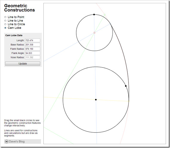
Geometric Constructions Page
The Geometric Constructions Page has a cam design feature that is used to design a simple engine valve cam. The Geometric Constructions page is used for my own experimentation but the cam design example is useful in itself. The thing that stands out when looking at the image above or at the page itself is that the cam being designed has a single lobe and some specific geometry that is not useful if a toy or automaton is being designed to have complex motion.
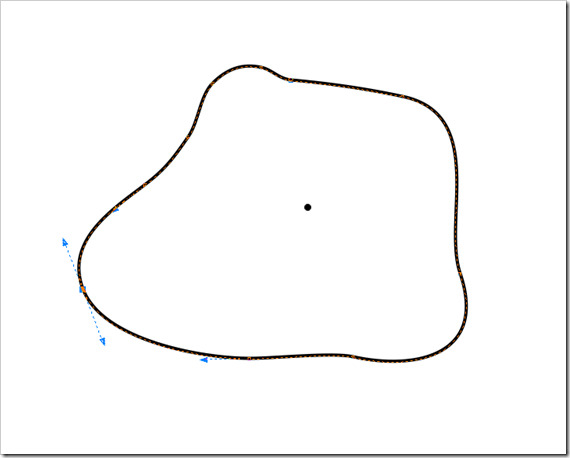
Toy or Automaton Cam
The toy or automaton cam seen in the image above is a quick drawing I made to show that the engine cam design tool would not work well at all. A Bezier curve editor is a much more useful editor paradigm in this case.
The cam design feature of the Linkage program will let the user pick the type of cam from a predefined set. I will start with just the engine cam due to it’s use of only circles and arcs to define the cam. Calculating intersections with connected parts of a mechanism should be fairly straight forward.
One interesting feature that I want to have in the Linkage program is a cam design window that shows the cam movement profile. It would be a graph view of the cam shape over time assuming a cam follower that is of the linear motion type. Cam followers that pivot change their angle in relationship to the cam lobe as they move in and out and are beyond my understanding right now. A simulation might be needed to establish the profile and editing the profile directly might be tricky when turning that shape into a cam shape.
Cam Profile View
The cam profile view is a good way to edit a toy cam where the position at a given time is meaningful. Being able to see the profile of other cams at the same time would be better when complex movements are needed. This might be beyond what I can add to the Linkage program right now but having multiple cam styles to start with and an visual editor that supports the profile or the actual cam shape, depending on the users preference, will be a good starting place.
The final piece of the cam puzzle is to allow the user to specify a cam follower type. At first, a round cam follower head will be the only type that can be used and it will only be used to show the actual cam shape as opposed to the follower “connection” shape. In other words, the mechanisms in the Linkage program are all shown with zero size to their parts and all connectors connect at the center of the pivot points. Since a cam cannot be defined this way and then manufactured properly, the path of the follower will be designed but the shape of the cam given a specific follower end radius will be drawn too within the follower path.
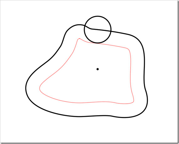
Cam Follower Path and Cam Shape
In the above image, the cam shape would be the red dotted line and the black cam shape is actually the path that defines the follower position. The circle would then be the follower end radius. My intention is for the user to define the path of the follower and the follower radius will be a setting for the cam.
This is still being developed and I don’t know how it will all turn out. The linkage program is a prototyping application and is not really meant to be a manufacturing design program. I’m not sure how to handle cam followers designs and other issues of that sort. They are much more complicated than sliding and pivoting connectors that need not have a size associated with them.
Dave


