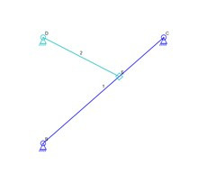
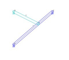
There are currently two ways to show links in the Linkage software: The link is drawn as a polygon using the outer-most connectors to define the shape, and drawn as a solid object with the connector circles giving the appearance of holes within a larger polygon with rounded corners. In the case of there being two connectors, the link will be drawn as a single line.
Links Drawn as Lines
Links Drawn Solid
Notice that the second set of links has a link with a dotted line down the middle. This is the path of the sliding connector. it was not necessary for the links in the first picture because there is already a line along the path. These representations work fine and will not change.
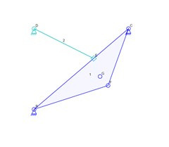
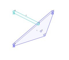
When links have more than two connectors, they are almost identical to the links in the above images except there are more lines used to define the polygon region that encloses the link. That outer polygon is called the “hull”. Links are still drawn similar to how they would be manufactured using the most minimal amount of material in either a solid out not solid fashion.
Link Hull as Lines
Link Hull Drawn Solid
The above images show how the links look when one of them has four connectors. Notice that connector G is within the area of link 1 and therefore has no line to it in either form. Links are not drawn withy concave shapes in the Linkage program. one reason for that is that it makes it complex to draw the link as solid. it also makes the internal order of the links meaningful. These are still fairly simple situations and for most mechanisms, these work as expected and look great.
Curved Slider Paths
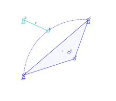
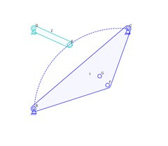
In the case of a slider path being curved, the current link drawing code is not complex and the curved slider path is not included when drawing the outer shape of the link. below are images that are almost identical to those above, but they have the slider following a curved path that extends outside of the hull shape of link 1.
Curved Slider Path Drawing
Curved Slider on Solid Link
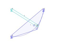
Now the shortcomings of the current drawing code can be seen. the slider path in both cases is a dotted line that isn’t inside of the link hull. This is the problem that I would like to fix. But with all problems like this, it’s not easy to handle every case. For the images above, I can probably calculate that the curve is convex and extends the hull shape. But if that slider path is curved the other direction as shown below, things get tricky! From this point on, I will only show pictures of the solid version of links because the problems are about the same in either case.
Slider Path Overlap Problem
You can see the overlap problem in the image above. The slider path is partly within the bounds of the hull but partly outside of it. In the case of a non-solid link, I might be able to detect where the lines intersect and draw along that outside path. It would be very difficult if there were multiple slider paths crossing each other and also transitioning outside of the hull. For a solid link, it’s even more complicated because I would not want to the slider path to be draw along the outer edge of the link, I would want the path to be a dotted line with more link area outside of it like when the path is straight.
I will probably write code that is necessary to change the simple version of this problem where two adjacent connectors of the hull are defining a curved path that goes outside of the hull area. For a curve the other direction or for a path that is between non-adjacent hull connectors or internal connectors, I feel like it would be too complicated to try to draw those in a visually appealing manner.
Fortunately, sliding connections are rare and I have only seen real-world mechanisms that use a single slider that is straight. Maybe I’ll get lucks and discover a simple equation that let’s me find a curve that would enclose the protruding slider path without sticking out more than is necessary. I’ll research that but I’m still not sure how I would detect the situation when that is needed.

