

I am about to add curve drawing to the Linkage program. The curves will be compound curves, or whatever you would call a chain of elements that can be lines, arcs, or Bezier curves. To start work on this, the first thing I did was remind myself how to draw a cubic Bezier curve that has four control points.
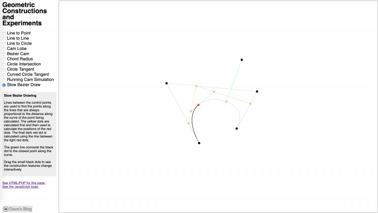
The geometric constructions page shown above is where I’ve done a few different experiments written in JavaScript. All of these use a framework I built for the page that makes some of the work fairly simple.
A cubic Bezier curve uses four control points. Although they are all used mathematically in the same manner, the first and last points end up also being the start and end of the curve and the other two points are never reached by the curve. Watching the animation on the page shown above makes it clear what is happening but I’ll describe it anyhow: To find any point on the curve defined by a number between 0.0 and 1.0 that represents its distance along the curve (1.0 being 100% along the curve), lines are created, mathematically or just in one’s imagination, between the first and second, second and third, and third and fourth points. Call these points A, B, and C. My code creates actual line objects so they can be drawn. Then a point is calculated along each line using that same distance number between 0.0 and 1.0. Lines are then created (in my code for drawing and to keep track of the end points easily) from points A to B and B to C. One last line is created and the point along it is calculated. That last point is the point on the curve as specified by the number between 0.0 and 1.0. To draw the curve, the code runs in a loop and steps through number from 0.0 to 1.0 to draw line segments between those points. The more steps there are, the smaller the segments and the smoother the curve. Optimized drawing code would figure out the number of steps based on the expected length of the segments to get the best looking curve without drawing extra segments.
It’s a lot to describe in text but it’s fairly easy to implement. In fact, al of the code I’ve written so far has been fairly simple.
To compute the point along the curve, it is better to use a little math and not actually create lines, real or imaginary. The code above draws the Bezier curve on my test page. I got the point calculation from somewhere on the internet – it is fairly common and seems to be the most optimal way to get the point along the curve. If you try downloading the code from my test page, you will see that I also create the lines and points so I can draw all of them for the construction animation.
The method of finding the closest point on the curve to some other point is purely iterative without any interesting math at all. There is supposed to be something more optimal available somewhere but I dread having to implement code to deal with Sturm’s theorem. My method simply divides the curve a small set of points and checks to see which point is closest to the test point. The code then takes the closest point and divides a section of curve around that point (half way to the point before and after it) into points. Those are all tested and the same thing happens again. I do this a few times to get fairly accurate results. When I implement this in C++ in the Linkage program, I’ll do some performance testing using a profiler and increase or decrease the level of accuracy of the algorithm as need to keep the program running smoothly.
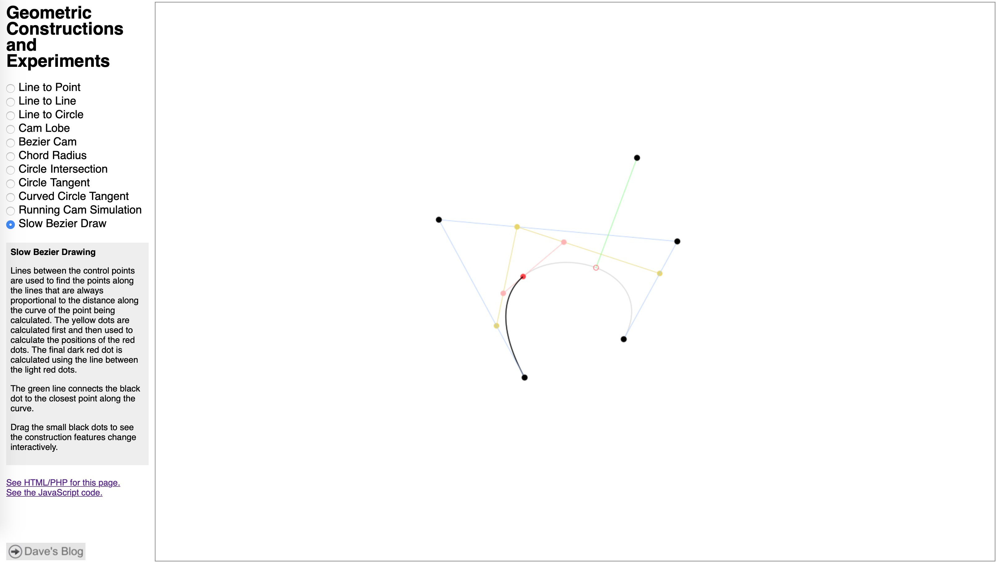
If you are paying attention and have some idea of how the code is working right now, you may notice that the points along the curve that are tested might be far enough apart to cause errors in some situations. The easiest situation to reproduce an error is when the curve crosses itself. In that case, there is always a point that will be fond closest to the wrong point not eh curve.

In the picture above, you can see that the red circle on the curve is not the closest point on the curve to the black dot connected to it with a green line. The happened because the points along the closer section of curve are still far away from the test point and don’t get picked because they are not as close as the point on the further away section. here’s a better picture that I hacked together to show what I mean. The points along the curve being tested are drawn as bigger redder dots.
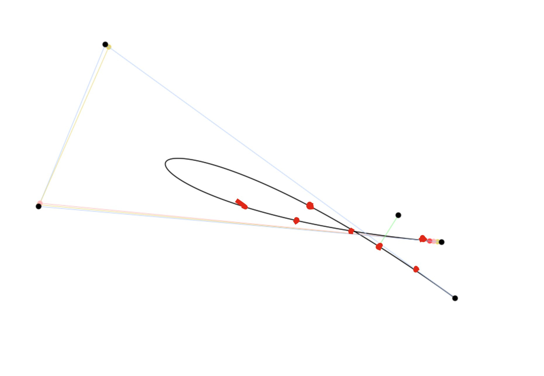
If those weird red dots I draw in there were the test points on the curve, it’s pretty clear that the picked location on the curve is closer than any of the other red dots. Of course, I draw this a little clumsily but the point should be obvious, that more points need to be calculated to reduce the possibility of this error. Also, if you are just hit testing to see if the user clicked on the curve, even a low number of point like this works perfectly fine and the error has no effect on the test. After all, if you are close enough to have clicked on the curve, it doesn’t matter which part of the curve the code thinks you clicked on.
The next step is to do a calculation of the intersection of a bezier curve and a circle. this will be required if I use these curves as paths for sliding connections. This algorithm should work fine when modified to find a point on the curve because no sane person will make a path that passes over itself like this. The algorithm will get modified to keep track of two points along the curve, one after another, and detect when a line between them could cross the radius of the circle. I will need to keep track of up to three such crossing since that is the maximum number that a cubic Bezier could cross the circle, if I remember correctly. For each crossing, the code will step through the section of curve that crossed and find a small section that crosses. After a few iterations of this, a simple line to circle intersection will get used to find the very closest point of crossing. I may post an update to this post or post again when that is working on the test page.
And finally, the Linkage program will support a compound curve like in CorelDraw where multiple line segments, Bezier curves, and maybe even arcs, are all chain able by having them share control points. I especially want to allow for arcs or some sort of chamfer or fillet feature so it’s easy to just pick a node or control point and have the code create an arc with a given radius visually. I’m not sure what all of those options should be.