I have a plan. It’s not a very good plan, but it is a plan.
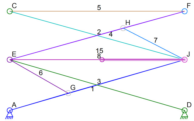
 The mechanism above presents a problem that I have written about a few times in the past. The EGJ triangle is what I call a “link triangle.” It is a set of links that when simulated, act like one larger link. Although I added some code to do some simple link triangle simulation, it is not at all what I need. That code was more of an experiment to see if I could detect a link triangle and then use it in a simulation. But it could not handle the actuator seen here.
The reason that the existing link triangle simulation code can’t handle the actuator, and is far too simple anyhow, is because I used a modified function to replace a regular link with some triangle link info while looking for links to rotate to meet each other. There was no way to actually simulate the actuator when creating the link triangle and no way to handle sliding connections. Damn those sliding connections – they made all of the simulation code 10x more complicated that it was before adding the sliding connector feature.
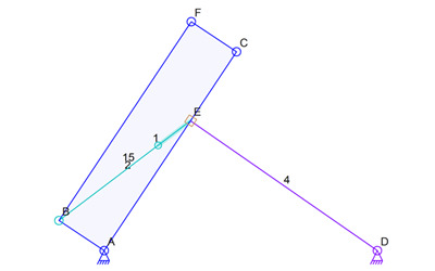
Above is another mechanism that has the same link triangle sort of problem. This one is a little more interesting because it only has two links in the “triangle” and one of them is an actuator. The simulation is easy to do on paper but is a very special case in the software.
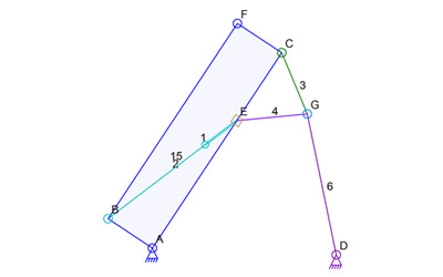
Now it’s just getting weird. Again, this is easy to simulate on paper but is yet another weird special case. The link triangle is formed by connectors CGE but the shape of the link triangle is defined by the actuator that is not a leg of the triangle.
So first things first. The only way to simulate this sort of thing is to figure out the relative positions of the various connectors based on the actuator length. Remember, what the mechanism looks like before it starts is not what it looks like at any step in the simulation. I will need find link triangles, and that non-triangle variation with the actuator and slider, and simulate the parts as if most of the connectors are at a fixed location. then I can create a temporary link of the new shape and use that in the normal simulation code to see how it interacts with the rest of the mechanism. I would need to save the temporary link and find other link triangles before doing any full mechanism simulation because two link triangles might be connected to each other.
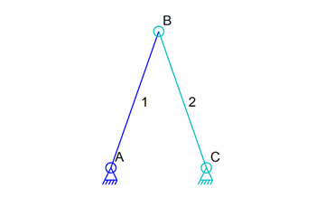
But first, I need to change the entire data structure of links and connectors. Look at the simple mechanism above and then at the XML in the data file:
<linkage2>
    <program zoom="1.000000" xoffset="-10" yoffset="0" scalefactor="1.000000" units="Millimeters"/>
     <connector id="0" selected="true" layer="16" x="-156.734694" y="54.666667" anchor="true" color="16711680"/>
    <connector id="1" selected="true" layer="16" x="-117.551020" y="166.000000" color="12632064"/>
    <connector id="2" selected="true" layer="16" x="-78.367347" y="54.666667" anchor="true" color="32768"/>
    <Link id="0" selected="true" layer="16" linesize="1" color="16711680">
        <connector id="0"/>
         <connector id="1"/>
    </Link>
    <Link id="1" selected="true" layer="16" linesize="1" color="12632064">
        <connector id="2"/>
        <connector id="1"/>
    </Link>
    <selected>
        <connector id="2"/>
        <connector id="1"/>
        <connector id="0"/>
        <link id="1"/>
         <link id="0"/>
    </selected>

</linkage2>
Notice that in the data file above, and in the internal data structures for the mechanism, there is a single connector for the place where the two links are connected. This was a tough design decision to make and it turned out to be a bad one. What it does is it lets the user select and move a connector with very little code. But it also makes it impossible to treat links 1 and 2 completely separately. If the code needed to move connector B to make link 1 longer, like if it is an actuator, but not change the location of connector B for link 2, it is impossible; there is only one connector B. This makes it impossible to create a temporary link in place of a link and then simulate it using different connector locations.
The plan as of a few minutes ago was to change the entire data structure so that each link keeps track of the connectors as separate objects in the code. There would be two objects for connector B, one belonging to each link. They would then point to each other. I think that these per-link connectors will not be connectors like I use now, they will just be some intermediate data structures that keep track of where they connect and also keep track of the existing connector data object. Ugh, too many objects in the data structure for the mechanism gets a bit unwieldy (if that the right word). It makes it hard to maintain the code when there’s so much data to manage and use during any operation.
So to put it another way, the connection points of a link will have their own positions along with a reference (C++ pointer) to the regular connector object. The regular connector objects will no long have a position used during simulation, just during drawing of the mechanism. I can then create a temporary link from a link triangle and have it connect to other links without worrying about altering the shapes or sizes of those other links.
Now to actually change the code. That’s going to take more than a few hours I suspect.


