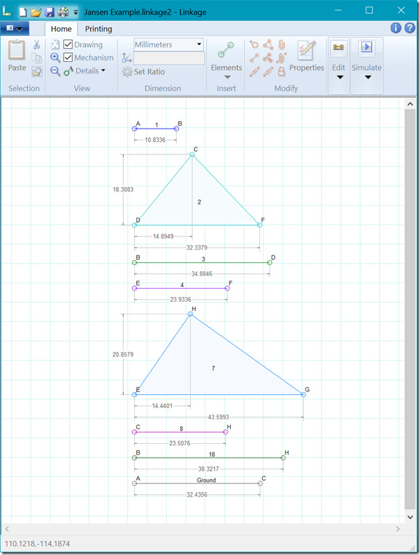
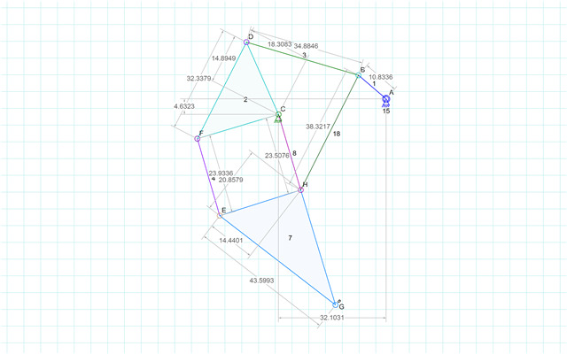
The parts list feature is almost done in the Linkage program.
Parts List
The parts list is a view of the mechanism where each link is shown in a “horizontal” position in a vertical list with all of the other links.
This has been a challenging feature to add because of a few limitations in my experience with document-view architectures (MVM I think) and because the Linkage program has a very interesting way of drawing part dimensions. I’ll explain…
The document-view architecture is a design paradigm where all of the data for the, well, Data, is held in a “document” object. All of the code that draws the data on the screen is in a “view” object. This keeps the document data from knowing about how it will be displayed. HTML was designed a bit like this, got broken along the way, and is now used this way thanks to CSS. Anyhow, my document holds the positions of all of the connections and the information about the links that have those connections. The problem is that this particular view requires pretty much a complete copy of a document (mechanism) with all of the links moved around to new locations. I opted to just create a temporary copy of each link as they are drawn on the screen. The copy has it’s own set of connectors that don’t actually connect to any other link. This works pretty well and it all happens in the view object code; the document code stays clean and free from view-related code pollution. Or almost free since I save some view info with the document on disk. Oh well.
The other problem was the problem of drawing dimensions. I draw the dimension lines a specific real-world distance from the links and connectors. This is sort of cool because zooming in doesn’t move the dimension lines further away from the links. After all, doing that would not make the program easier to use and maybe harder to see the dimension lines. I certainly don’t want to have them too close to the links and connectors and I really want to avoid making the user move them around ever! The solution is to recalculate the locations of the temporary links every time the mechanism is drawn. Since there is no way to run a simulation in the parts list mode, there is no way to see that it slows down the display by a fraction of a second (I never bothered to measure but a simulation would probably run fine).
With these problems solved, and with the addition of some code that uses the actual drawing to pre-compute the size of the mechanism, display, export, and printing of the parts list is almost perfect. Ok, so some text isn’t included in the document area computations and gets cut off in the print preview and printouts; nothing is perfect.
The Original Jansen Mechanism
I will make a beta version available shortly. I’m not sure if the parts view is just another item for the “Details” menu, or if it needs a big button to enable/disable it. What would be really cool is to switch to that view if the user picks a “parts View” tab in the toolbar. then I could have some parts-view-specific options there.


