
It took me a few minutes to figure out the difference between Escapement and Orientation when using the CreateFont() function. Actually, it took me about 2 seconds to figure it out once I had seem discussion about it and heard about people trying to create some sort of orientation change for their text. One defines the orientation of the line of text and the other defines the orientation of each character.
In other words, This:
![]()
Is not the same as this:
![]()
Yet both of these are not typically oriented. To be honest, I am writing this before I have figured out which of Escapement and Orientation controls character and line orientation. Since my intent is to keep the characters and the line matching, I won’t need to know the difference and both values will be the same.
I will be adding measurement capability to the linkage program. I had an interesting discussion with someone about this and my curiosity was piqued when I was told that only some parts of the drawing should show measurements and not others. Why would someone do this? It turns out that if your drawing has parts in it that already exist in the real world, they will not be built and therefore do not need to show measurements. Still, showing all measurements will be an option.
Oh, and the act of displaying a measurement is called “dimensioning.” This is strange to me since the dimensions are not being set, just displayed. To “dimension” a part doesn’t mean that the dimension is being changed, just displayed. This type of wording is strange to me and I am always cynical about the source of such thing. Sometimes programmers just make stuff up for the hell of it and their design skills or skill at writing and using terminology are far less than their programming skills. Programmers seem to think they know everything about a subject just because they can write a program in that area of study.
None of the text in the linkage program is of a non-standard oriented, it is all at 0 degrees (or 90 if you’re into math). so it reads just like any newspaper or book. One idea is to keep the orientation this way for measurements as can be seen in the next image (that I took from the internet).
Always Horizontal Text
The other idea is to orient the text along the measurement lines as can be seen in this next picture. This will be harder to read without good anti-aliasing and a reasonably sized font.
Text Oriented to Match Measurement Lines
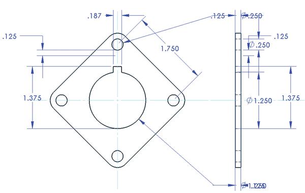
I will attempt to orient the text to the measurement lines. I will also allow the user the opportunity to select which parts need measurement. If the user selects two connectors then the measurement will be between those two connectors even if the measurement changes and the mechanism moves. If they select a link, I want to make a measurement between the two most distant connectors on the part and then show a measurement along that same angle to the other connectors. Here is a hand-made example of a three connector link and how it should be measured. Note that this is to help someone make this part using typical tools like a tape measure and hand drill, or if they are lucky, a mill.

Sample Link Measurements (With Made Up Numbers)
I am not sure if the measurement lines should ever overlap the link but the idea should be clear from the picture. There will be a baseline and then all other measurements will be made from that baseline.
Along with measurement display capabilities, I will also add exact positioning capabilities. This will allow a person the ability to position a connector in an exact location relative to the zero position in the document or to another connector. I will probably take some advice that was given to me and add a text entry field to the status bar that can be used sat any time to enter either a distance or a set of coordinates and the selected element will move appropriately depending on what type of information is entered.
Dave