I’m not sure what to call them. On an actuator, there is a small circle that can be used to change the throw length. That little circle is an adjuster knob or adjustment controller or something like that. I’m working towards in-mechanism editing of cams and changing the code to support those on any element is part of that work.
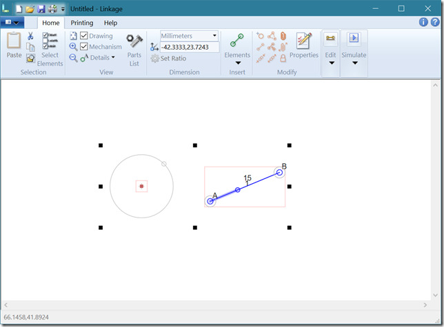
The first big change that is visible to the user is the addition of an adjuster knob on the drawing circle. The drawing circle is a drawing point element that is set to include a drawing circle. When the point is selected, the little adjustment knob circle will appear and can be dragged around.
The second big change is that I am making the adjuster knob on the actuator only visible and selectable when the actuator is selected. from now on, adjuster knobs of any sort are only visible when the element is selected.
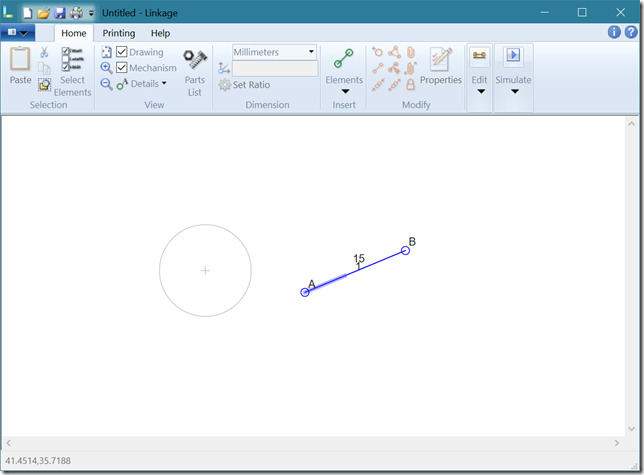
Circle and Actuator “Un” Selected
Circle and Actuator Selected
Notice in the first picture that the actuator doesn’t have the little circle at the end of the “cylinder” portion of the drawing. Also notice that when either or both elements, the circle and the actuator, are selected, the adjuster knobs are visible. Either of those adjuster knobs can be dragged with the mouse when they are visible and it will not unselect the elements.
This is important work because there will eventually be a few types of cams in the program and they will all be modifiable right in the mechanism window. Of course I will also have some types of cams provide special properties boxes that let users set some properties by entering numbers (especially needed for engine valve cams) so this won’t be the only way to modify a cam. But for a cam with a variable number of Bezier curves defining the shape, having these controls is the only way to design the cam shape.
I am still testing this work and it might change in the future. I might also add adjuster knobs to other elements if there is any reason to do so; maybe chain sprocket size should be settable this way.


