I had a user send me a mechanism that they thought should work. It turns out that none of the connectors were forming connections between links. I plan on making a tutorial about common problems like this and I’m writing this post in order to help those who are just reading my stuff or searching for it.
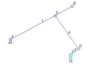
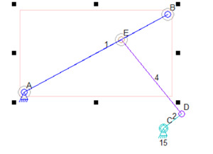
Here’s a mechanism that looks good and should work:
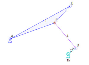
But running the simulation does the unexpected and produces this:
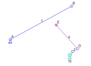
The problem is that Connector E only looks like a connection between Links 1 and 4. It is especially hard to tell when the colors are so similar. But in fact, Connector E is simply the end of Link 4 and is only positions on top of the line of Link 1.
So how do you detect when you’ve made this mistake? Aside from just selecting Link 1 with the next version of the Linkage program and seeing that Connector E is not circled, you can drag Connector E.
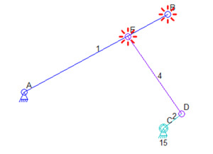
First, here is what Linkage 3.2.7 will show when selecting Link 1:
Notice that Connectors A and B are both circled. This is the new feature to show circles around connectors that are part of a selected link. Connector E is not circled. If you drag Connector E, you would see that it is not part of Link 1:
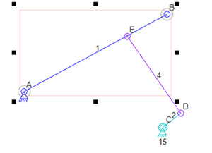
So how would things look if that connection was really made between Links 1 and 4? Selecting Link 1 would look like this:
And then dragging Connector E would now have the expected effect of changing the shape of Link 1:
So keep an eye out for connections that just look like they should work. The software is made to make things easy but there is no way to know that a connector drawn on top of a link is supposed to make a connection at that point.
And I’ll update the installer to install version 3.2.7 shortly after I post this.
Next on the agenda? Adding more useful error symbols and messages. Sometimes the software can know what is wrong with a mechanism and it should draw a little arrow and print out some text describing the problem.

Thank you for this improvement Dave. I have been caught off guard by this very thing several times.